Category Archives: Issue 26 (October 2014)

The Editor

Welcome to Issue 26, October 2014!

We’ve probably had the best of the season’s weather here in the UK, albeit there is talk of an ‘Indian Summer’ in September and stretching into October. It has certainly felt like it during this past week (week commencing Monday 1st September).

I’ve just come back from the TTT 2 Tour of the Isle of Wight which was enjoyed by 45 cars and their owners. Lots of positive feedback has been received and the following comment is not untypical:

“For us, the format was spot on, with enough time in the programme for prolonged stays at places of most interest to us, and of course a delight to meet many old friends and an opportunity to make new ones too”.

At the Saturday evening dinner I was presented with a tissue box to hold tissues which are used to wipe the dipstick when checking the oil. However, this is no ordinary tissue box; it is one made from several different types of wood by retired Furniture Maker and Designer and long time TC owner, Martin Franklin. On one side of the box (the sides are made from Sycamore which comes from Wormshill, Kent) is an engraved Octagon made from Holly grown in Hollingbourne, Kent. Certainly the work of a master craftsman and one which I will treasure.

<

The contents of the box were also interesting – several bank notes which are to be used to further the cause of T-Type motoring. They will be used wisely and I shall report back when I have decided what to do with the contents.

Paul Ireland has uploaded a video of the Tour to YouTube:

With no ‘cover story’ article this month, we decided to reach out to the followers of our MG T-Types Facebook page and ask them to send in their favourite photos of their cars to grace the front cover. Thank you to everyone who provided photos; the contributions were excellent, and we hope to publish many of them in future issues and/or on the MG T-Types Facebook page.

This issue’s cover features our favourite of those contributions: a photo sent in by Mike Killingsworth from Australia. Mike bought TC1918 in December 1971 as a “present” to himself for getting his Navy Wings. As a junior pilot posted to VS 816, a Grumman Tracker squadron, he managed to convince the captain of HMAS Melbourne that he should be allowed to transport his TC from Melbourne (city) to Sydney after it had been stored at his parent’s home during the squadron’s deployment to Singapore. Some fun photos then ensued whilst at sea! He still owns the car, albeit now fully restored (twice), and uses it regularly.

THE 2015 TTT 2 TOUR – LANCASHIRE LANES AND YORKSHIRE DALES


The 2015 Tour is already fully booked and a waiting list has been started. At the time of writing (6th September) there are four on the waiting list.

Mindful that there is likely to be even further demand for the 2015 Tour, Grant and Barbara Humphreys, our joint organisers, are going to see if we can accommodate a few more, albeit this is going to be seriously challenging.

THE 2016 TTT 2 TOUR

As stated in the previous issue, the venue/area has not yet been decided The Malvern Hills might be a good test for the cars, not to mention their occupants!

Appointment of new DVLA representatives for the MG Octagon Car Club

I have agreed to act as the DVLA representative for the Club, along with Pete Moore, the Secretary. We can help you to obtain an age related registration number and also assist with the V765 procedure (reclaiming a ‘lost’ registration number). I have had excellent tuition from Roy Miller, who knows a lot more about the ‘ins and outs’ of this business than most. Thank you Roy!

Sale of TC0301 (Registration number FTL 60)

John Steedman is offering for sale his very early TC. An advert appears later in this issue. This is an outstanding opportunity to acquire an immaculate TC at a fraction of the cost of a rebuild. Yes, it needs engine work but it is realistically priced. Hurry because it will go quickly!

JOHN JAMES


DISCLAIMER BY THE EDITOR

Totally T-Type 2 is produced totally on a voluntary basis and is available on the website www.ttypes.org on a totally FREE basis. Its primary purpose is to help T-Type owners through articles of a technical nature and point them in the direction of recommended service and spares suppliers.

Articles are published in good faith but I cannot accept responsibility or legal liability and in respect of contents, liability is expressly disclaimed.

Problems with Modern Fuel?

Last year a student project at Mechanical Aerospace and Civil Engineering Department (MACE) of Manchester University was sponsored to mount an XPAG engine onto a dynamometer and use this to investigate the running problems many owners experience with modern fuels. Unfortunately, timescales meant this work was not completed; however, there was time to run limited tests.

When running the tests, during the part load tests, the relative float height of the suction pistons in the two carburettors were different, indicating they were no longer in balance. What was striking was the degree of out-of-balance depended on which fuel was being used.

A part load test – engine running at 3000 rpm and 3⁄4 throttle using Esso 95 octane.

At the time we had no means of measuring the float height of the suction pistons, so part way through the tests I started taking photographs with the intention of making measurements from these.

In practice this was not possible; however, to my surprise, when you blow up the photographs and digitally enhance them, you can see something very interesting that may explain the problems we are experiencing with modern fuel.

With SU carburettors, the float height of the suction pistons is a measure of the volume of air entering the engine; the front (right hand) carburettor feeding cylinders 1 and 2 and the rear cylinders 3 and 4.

While the carburettors were balanced at full throttle, there is no guarantee they will remain balanced at part throttle. The quality of the XPAG cylinder head and manifold castings is poor with differences in both the size and shape of the cylinder ports. The cylinder head of the engine under test has not been gas flowed nor have the inlet and exhaust manifolds been matched to the cylinder head. As a result, changes in turbulence in the inlet and exhaust tracts between cylinders 1 & 2 and 3 & 4 could alter the gas flow and hence the balance at different throttle settings. What is surprising is that the balance also changed when using the different fuels.

The two photographs, below, were taken with the engine running at ¾ throttle and 3000rpm. The top picture using E10 bought in France, the bottom Esso 95 octane. You can clearly see the height of the piston on the left hand side is higher than that on the right in both cases. This indicates more gas is flowing into cylinders 3 & 4 in comparison with cylinders 1 & 2. However, the piston of the right hand carburettor is noticeably lower in the bottom picture (Esso) than in the top (French E10).

With the same throttle setting and rpm in each case, the most likely explanation is that the increased difference in balance must be due to the fuel. It was the only thing that had changed.

How can this be?

On a standard XPAG engine, the inlet valve starts to open 11o before TDC and the exhaust closes 24o after TDC. For 35o both inlet and exhaust valves are open. This valve overlap allows the rush of exhaust gasses out of the cylinder to start the induction of the next air/petrol charge. Differences in combustion profiles between the cylinders, especially late combustion, will affect the pressure in the cylinder when the inlet valve opens and hence the volume of gas flowing through the carburettor. In the worst case, exhaust gasses could flow back into the inlet manifold. The dispersion of the fuel and combustion process depends heavily on turbulence. On the test engine, it is very likely there is a difference in turbulence between cylinders 1 & 2 and 3 & 4 and hence it is possible that the combustion process and back pressures could also be different between the two pairs of cylinders.

If this explanation is correct, the differences in piston heights is a direct comparison of the average combustion in cylinders 1 & 2 versus 3 & 4 and suggests E10 is burning better than the Esso 95 as the pistons are higher (more air flowing into the engine) and the carburettors are better balanced.

This is where the enhanced photographs tell a very interesting story.

The photo below shows the blown up sections of the rear carburettor from the pictures previously shown. They clearly show the fuel leaving the jet, entering the airstream and passing over the top of the butterfly. The fuel has been artificially coloured red to make it clearer.

Two features are obvious. The first is that the piston is floating higher with the E10 than the Esso indicating a lower back pressure and hence better combustion. Secondly, and more importantly, the dispersion of the E10 into the airstream is considerably better than the Esso.

Even though the atomisation of the E10 is not good, the Esso is considerably worse looking like there is virtually no atomisation or dispersion of the fuel as it leaves the jet.

Poor dispersion of the fuel in the carburettor, will lead to poor mixing and vaporisation in the cylinder which in turn will lead to slow combustion, higher back pressure during the overlap of the inlet and exhaust valves and lower air flow through the carburettor, consistent with the observations. It would also explain why not all cars suffer from the problems to the same degree. Variations in the inlet manifold will produce different levels of turbulence in the same way that cylinders 1 & 2 are affected more than cylinders 3 & 4 in the test engine. It is likely the carburettors performed well at full throttle as there was sufficient air flow through them to better atomise and disperse the fuel. The loss of balance only showed itself on the ½ and ¾ throttle tests.

Is this the problem with modern fuel and is there any other evidence to support this? Previous tests and observations lend support to this hypothesis.

Firstly, the acceleration tests and exhaust temperature tests performed by David Heath and myself suggested the engine needed to be significantly advanced (“Modern Fuel On Trial”). Poor mixing at the time the spark plug fires will slow the initial growth of the flame front requiring the engine to be advanced in order to run properly.

Secondly, my two-tone plugs. After fitting long nosed plugs, I noticed that one side of each plug facing the inlet valve, looked like new. This is caused by the fuel entering the cylinder “washing” the plug clean; another indication of poor dispersion. The following picture shows the brown half of plugs 1 and 3 and the clean half of plugs 2 and 4 counting from the left.

Perhaps this finding is not surprising. Modern fuel has a higher specific gravity than “classic” fuel, it is denser and it consists of a greater fraction of heavy distillates. All these factors make it less likely to break up when it leaves the jet. The challenge now is to confirm these observations and evaluate possible solutions.

Paul Ireland

Keeping it on the straight and narrow – Aspects that affect TA/TB/TC steering (Part 7)

Eric Worpe delivered a superb presentation at the MGCC ‘T’ Register’s ‘Rebuild’ seminar in March 2013. Eric used flip charts to aid his presentation and I have been working with him to ‘flesh out’ the flip chart notes to produce a series of articles for inclusion in TTT 2.

Eric divided up his presentation into seven headings which he termed as “Seven Deadly Sins”. We have so far covered the first six ‘Deadly Sins’ i.e.

CHASSIS – is it true? – Issue 19 (August 2013).
FRONT AXLE GEOMETRY – Issue 20 (October 2013)
FRONT SPRINGS – Issue 21 (December 2013)
KING PINS – Issue 22 (February 2014)
TRACK ROD AND DRAG LINK ENDS – Issue 23 (April 2014)
TYRES AND TRACKING – Issue 25 (August 2014)

In this issue Eric covers the Bishop Cam steering box. Over to Eric:

I often find myself resisting the urge to waggle the steering wheel of any TA/B/C that I come across just to see how much “free play” exists. It was only after trying the waggle test on a WW2 Willys Jeep that had over 4 inches of play that I realised why there was such an acceptance of T-Types by American GIs.

Although free play is not the only component of a nomadic steering system, it certainly amplifies other faults and promotes considerable skill and concentration from the driver to avoid over-compensation in steering. The Bishops Cam (BC) box should be set up for minimum play (# pinch) when the sector arm’s peg is in the centre of the track formed by the worm’s groove (Fig.1 on the next page), corresponding to the straight ahead position of the front wheels. The peg in this position seemingly has an “optimum mesh” with the groove.

If only it were that simple!

The peg scribes an arc as it moves along the track, tending to disengage its mesh as it swings away from the centre, leading to increased free play. However, this characteristic is complicated by an unusual feature of the BC box. I’d assumed that when the peg was in the centre of the track, its position would be vertically above the centre line of the worm’s axis; this is not the case as it actually overhangs the centre by almost 1/8 inch (see photo 1).

Photo 1 – illustrating how the peg overhangs the centre line of the worm’s axis.

This leads me to believe that there’s an ingenious relationship between the peg’s “overhang” and the taper angle used on the groove and peg that sets up an extended “optimum mesh” in the centre of the worm’s track. This relationship was revealed by a “rebuilt” box that I’d bought from Toulmin Motors in the 1960s. The box had a replacement worm and peg machined by a local engineering workshop which used a different taper angle. This resulted in two “pinch” points either side of the centre where the gear’s mesh was optimised at the expense of some free play in the centre.

Further investigation of the relationship between the peg’s position along the track and the level of “free play” suggested that the groove is not parallel. So, our simple BC box has a few tricks up its sleeve that were not always appreciated by those re-manufacturing spare parts. Photo 2 shows a test rig that measures the displacement or “end float” of the sector shaft as its peg moves along the track.

Photo 2 – the test rig referred to in the text.

Having surprised ourselves with the discovery of some possibly ingenious design aspects of the BC box, we now find that some less than sound engineering practices take over. The oil-seal at the bottom of the sector shaft’s housing consists of an interference fit cork ring whose effectiveness is limited, especially when play develops between the sector shaft and its housing. The subsequent oil loss can accelerate wear considerably due to the high levels of friction within the box, unless the box is “topped up” regularly.

The BC box is made from a malleable grey cast-iron which is stronger than basic cast-iron, due to some of the free graphite being “burnt out” by keeping the box at red heat for a long period directly after the casting operation. This unfortunately leaves it a less than ideal bearing material for the sector shaft, which would have been heat treated for toughness at the expense of a surface hardness level that would have reduced wear rates.

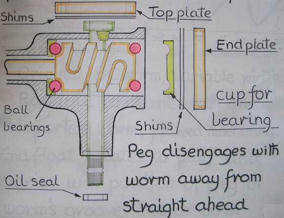
On a more positive note, the worm gear is carried between two sets of ball bearings which are “pinched” together to eliminate play by an end plate clamped to the main body of the box by 4 BSF bolts. Judicious choice of shims sets up the right “pinch” effect (please refer to Fig. 1).

Fig. 1 – showing ‘cut-away’ illustration of the BC steering box.

Graph 1 (below left) shows the relationship between the “end float” and the position of the sector arm. The pink line is from an original BC box and the orange line is from a replacement part having a parallel groove, which progressively increases play as the peg moves towards the end stops.

Graph 2 (below right) shows some serious machining problems in a batch of worms that had to be rejected, re-machining spare parts to high levels of accuracy calls for considerable effort and skill in setting up production for quite small batch numbers.

The sector shaft’s arm carries a hardened fixed peg which runs in a case-hardened groove machined in the worm gear. The peg’s taper creates an upward force which is countered by a slightly hardened top plate secured by 3 BSF bolts to the body of the box. One of the bolts should be drilled to allow oil (EP 140) to be pumped through a grease nipple into the box. Once again shims are used to set up the mesh of the peg in the groove so as to eliminate play.

Some modified top-plates are available that set the peg’s mesh by use of a thrust bearing that’s positioned using a threaded adjuster in line with the sector shaft. This produces a bending moment on the sector arm which has resulted in fractured arms (Photo 3).

Photo 3 – the fractured sector shaft referred to in the text (photo by kind permission of Werner Hofstetter).

If you have such a modified top-plate and find that the box has started to need frequent adjustment to reduce play, DO NOT delay replacing the sector shaft with a modern steel alloy replacement. Even if there are no signs of a fracture and you chose to continue using a modified top-plate, then at least consider replacing the old sector shaft before any signs of a fracture or of twisted splines occurs.

As part of the peg wears, two shoulders are formed such that when top-plate shims are removed to reduce play, the shoulders are thrust into contact with the edges of the worm’s groove. These localised pressure points can then break up the case hardened skin of the groove’s edges. This problem was eventually diminished by chamfering the worm’s edges, an operation not carried out on modern replacement worms unfortunately.

Considerable force is exerted by the box on its fixture to the chassis. Waggling the steering wheel whilst observing the box may well reveal a lack of rigidity, especially between the steering column’s outer tube and the box. These were originally locked together by an interference fit, but most have probably been braised together for robustness, which can be compromised if the bracket securing the outer tube to the scuttle is not secure.

The box pivots around a 3/8” bolt supported by two lugs on the bracket attached to the chassis. The holes in the lugs tend to elongate, but these can be drilled out to 10mm as well as the box’s support section, to take an HT 10mm bolt which may help reduce play. Choose a bolt length whose unthreaded shank just passes through both lugs.

It’s possible to overhaul the BC box by boring out the sector shaft’s housing to take either an oversized shaft or bronze bushes and a spring loaded lip seal. However, as clearance for the worm gear encroaches on an area of the housing that should be used to support the sector shaft, boring out the housing any further weakens support in a crucial area.

The VW Conversion

This seems to be a contentious issue so perhaps it should be left to the individual to decide after trying out a VW conversion on, say, a friend’s TA/B/C.

The VW box follows a similar design to the Marles-Weller box where the fixed peg of the BC box is replaced by a roller disk. This then follows a complex groove machined in the worm gear which is waisted in the middle and is supported by two sets of ball bearings (see Fig.2).

Fig. 2 – showing ‘cut away’ illustration of the VW steering box.

Instead of engaging the worm’s groove from the top, the VW box meshes its rotating disk slightly above the side of the worm, allowing the sector shaft to be supported by a top bearing (possibly a ball race) as well as a bronze sleeve bearing in its lower section. Such an arrangement greatly reduces friction between the worm’s groove and “follower”. Side thrusts experienced by the sector shaft are amply supported by bearings either side of the thrust force vector. An adjustment screw alters the mesh between the roller disk and worm gear allowing play to be minimised in the straight ahead position.

Gains and losses of the VW conversion

1. No permanent modification to the TA/B/C.
2. Reduced friction, wear and play.
3. Robust, well engineered box.
4. Less effort to steer.
5. Wedges can be removed, increasing stability.
6. Does not look too “out of place”.

On the other hand:

1. More turns lock to lock.
2. Slightly increased turning circle.
3. Likely to perturb some enthusiasts.

One criticism often put forward is the loss of the “classic car” feel, but the steering box is only one part of a suspension system based on cart springs, adjustable track rod ends and solid front axles all forming a rather basic steering geometry. With a VW conversion, steering is not only easier, but a greater sense of confidence in coping with the unexpected can be felt.

Numerous suppliers offer the VW conversion, but it’s not beyond the abilities of a competent small workshop to undertake the modifications to the VW box.

Some suppliers of parts for conversion:

VW box 111-415-061/A: vwheritage.com
Adaptor bush and splined shaft section: Roger Furneaux roger.46tc(at)virgin.net
Drop arm: mgsparesandrestorations.com (Andy King)

Farewell to ‘The Seven Deadly Sins!’

Well that’s the end of this series which I hope has helped fellow TA/B/C owners to sort out some of the beachcomber steering tendencies.

Eric Worpe

Photos from the 2014 TTT2 Tour of the Isle of Wight

Sue-Melville Smith from Australia came along in her YA, accompanied by Anthony Hillier.

Patrick Michel and Christiane travelled from France in their TC.

Rolf Schmidt and Sylvia travelled from Germany in their TC.

Pete Cole and Gillian Smith in their TD just leaving Calbourne Mill.

A view of some of the cars parked at the hotel.

Noel Lahiff and Terry Baulch in Noel’s TF. They used Terry’s TD the next day.

George and Pauline Arber travelled down from Chesterfield in their TC EXU.

Richard and Anne Holl’s TA in the foreground next to Paul and Christine Ireland’s TC.

This goose was determined to have a ‘slice of the action’ at Calbourne Mill.

Cars at Adgestone vineyard R to L: PB John James, TC David Lewis, TA John Philps, TD Ian Wells, TC Martin Franklin.

John and Sandra Vinnell enjoying afternoon tea at Calbourne Mill.

Jerry and Jo Birkbeck’s YT in the hotel car park.

T-Types at the Botanic Gardens in Ventnor.

Carisbrooke Castle where Charles 1 was held.

A farewell photograph of John and Sue James with Patrick Michel and Christiane Kondoszek.

T-Types are pretty reliable – except for when the crank breaks…

MG TC Brake Rod

The rod connecting the brake pedal and master cylinder on the MG TC has an articulation joint to allow for angular mismatch between the two components through the pedal travel when operating the foot brake.

The articulation joint on the rod removed from TC0894 during my ground up restoration was completely seized and that is no surprise as this small ball joint is fully exposed to the elements and all manner of road dirt.

I therefore considered it wise to add some modern protection to the joint by way of a flexible rubber cover.

After fruitless internet searches for something suitable I made a visit to a local breakers yard. Modern car engines are fitted with an array of sensors and the connectors to these, on some vehicles, have concertinaed rubber boots to keep out moisture.

On a Volvo I found a suitable looking item that cost me nothing.

After removing a small unwanted section of the boot it was slipped onto the rod (from the master cylinder end) with the aid of a little WD40 for lubrication and fits perfectly allowing the joint to move and provide protection.

I took the opportunity to add a little more grease around the joint as well.

The boot can be slipped on and off the hexagonal feature easily to allow adjustment and tightening of the brake lever lock nut.

The pre- and post-fitment can be seen in the photos.

Above and Below: pre- and post-fitment.

Steve Cameron
TC0894 (under full restoration)

Restoring the Advance Curve

I just bought my 1953 MG TD in Great Britain a few months ago. The engine was performing at best when I was in the original cool climate of the make. But arriving in Toulouse, South of France, I noticed the engine was dangerously knocking at high revs; maybe due to being in a climate with much higher temperatures?

I discovered that the distributor was the faulty part. The secondary spring of the advance plate was always loose even at maximum advance. And the root cause was the toggle that was worn where the spring catches. This was easy to diagnose because the hole is much more a slot. The other end of the slot has never been used and clearly shows the initial size. A few tenth of millimetre is enough to alter the advance curve. This kind of wear can only lead to more advance than originally.

The solution was quite easy. I made a plug out of a brass plate that exactly fits the long hole of the toggle, ‘tin welded’ it inside and drilled a 1.5mm hole. I chose to drill it next to the centre and further adjust the position with a rats tail file. The position was adjusted so as the spring action just begins at 7 degrees advance according to 40367 advance curve. The distributor on the workbench, this was measured with a protractor and with only one weight fitted on the advance plate.

The picture above shows, from right to left, the little bronze plug, the toggle which is worn on the left side, and the final assembly drilled and file adjusted. The other toggle was also worn but not so much. The primary spring hole was then adjusted to initiate tension of the spring at 0 degrees advance. This position would probably need a strobe lamp for precision. 0 Euros, a few hours and the car does not ‘pink’ anymore.

Laurent, France

Ed’s note: The TD in question is TD29133 which was mentioned in the previous issue of TTT 2 in connection with some gaps in its history.


Bits and Pieces

Oil drip trays

Originally developed and sold by David Pelham, these Oil Drip Trays have now been fitted to well over one hundred cars; orders have been received and fulfilled not only in the UK but also in Continental Europe, Australia and the USA. Response has been highly favourable. The oil drip tray is made from aluminium, weighs approximately 230 grams and has a 3/8 inch BSP drain with a 5/8 inch hexagonal drain plug. Earlier versions (pictured below with the finned sump had allen key drain plugs) The latest Drip Trays are first ‘Laser Cut’ to ensure accuracy before welding.  They have a capacity of 250ml, which means that even with the ‘leakiest’ XPAG the drip tray should not require draining too often.  They can be painted to match the sump and really do not look out of place; it could almost be an original fitting. The cost is £53 all up including Postage and Packing and can be obtained from bryan ‘at’ bryanpurves.co.uk

Above: early version (which has been painted) with Allen key drain plug.Below: current version with a 3/8 inch BSP drain with a 5/8 inch hexagonal drain plug.

Ed’s note: David Pelham, who originally brought these to market, died last year. His stock of drip trays was purchased by Bryan Purves. Since David’s death I have had a steady stream of enquiries which I have passed on to Bryan. However, I thought it would be useful to advertise their availability once again.

I think that the all-in cost quoted (53 GBP) only applies to UK orders. Postage outside of the UK would be extra.

TA-TC and TD-TF carpet sets

James Collingburn (son of Mike) has asked me to mention that they are making as original TA-TC carpets and TD-TF carpets and accepting orders for them. Customers can email: collingburn ‘at’ btinternet.com or Tel: 01748 824105. The photos show the TA-TC sets.

TYRE SIZES FOR 19” WHEELS

Dieter Wagner has sent in some comments following publication of the tables of tyre sizes for MG TA/TC in the last issue.

“I always recommend to the tyre size 4.75/5.00 x 19 for MG TA/TC. I think these have some advantages about the original size 4.50 x 19 and they fit without problem to the original wheels. They have one row more on the rubber, so better road holding, more comfort, you save approx. 3% revolutions and they are better looking on the car.

They are more expensive but last longer.”

Ed’s note: A number of items have unavoidably been held over until next month due to lack of space.

MG TD Clutch Linkage

We all know about the problems associated with the TD/TF clutch linkages and the rods bending and breaking. This is a fully adjustable linkage that I made up to eliminate this problem and I am currently testing it on my TD. It is made up using stainless steel turnbuckles, rods and nuts. (It is far from easy to make threads on stainless steel rods!). Two brass bushes are turned to fit the original lever. This seats the rose joint via an Allen bolt and nyloc. The drawing (following page) shows the new hole location for the Mike O’Connor modification which really smoothens the clutch operation. The whole arrangement fits quite nicely. Fine adjustment is via the turnbuckles. Although it probably not the cheapest solution it should last forever and minimize the risk of breakage. I am considering making up some kits.

Declan Burns

Email: declan ‘underscore’ burns ‘at’ web ‘dot’ de. (It is very hard to see the underscore when the link is highlighted: [email protected])

Ed’s Note: Declan has just updated the information in his article; the photos he mentions are included on this page and the updated drawing is shown below. “I have managed to find a rose joint which will actually fit inside the pedal box. With the rose joint you can eliminate the play on the pedal. I have updated the drawing and taken a few photos of the installation. Next job will be a gaiter to stop any ingress of water through the hole in the front of the pedal box.”


Click diagram for bigger version

MG TC For Sale

FOR SALE: MG TC 0301, 1945 This TC underwent a 7 year, nut and bolt restoration, completed in 2003. It also featured in a number of early TTT articles. At the time no expense was spared to achieve a concours level restoration based on originality. Unfortunately, due to a defective fastener in the engine, both the block and sump have been damaged beyond repair. Currently the engine is out of the car and dismantled. A replacement block and sump have been purchased, however other commitments prevent me from completing an engine rebuild. As a result I am offering the car and all engine components including replacement block and sump for sale. Offers are invited in the region of £18,000. This offers the purchaser to opportunity to acquire a superb TC for a fraction of the cost of a full rebuild. For more information, please contact John Steedman at johnhwsteedman ‘at’ aol.co.uk or 07899 9757022

Automotive Car Creeper

There is no doubt that all of our “classic” cars are getting older and therefore oblige us to keep up the maintenance schedule, in order to stay safe on today’s busy roads. Also, as time goes by, it seems to get that little bit harder to deal with all those checks, grease points, adjustments and repairs that require us to venture right under the car itself.

I have occasionally seen the so called “car creeper” devices advertised, that allows one to lie down and “roll” under the car with little effort and in some comfort. With this in mind I thought it might be interesting to make my own car creeper to ease the task of under chassis maintenance.

A relatively simple wooden design with 4 castor wheels and a headrest was drawn up, one which would not take up too much room, but would enable one to move effortlessly around the garage at floor level.

The car creeper described here is designed with 4 castor wheels and a headrest. The design is made taking up minimal height above the ground whilst still allowing very easy movement on a relatively flat surface.

My creeper is made primarily of 3⁄4” pine wood, but any timber could be used as long as it has sufficient strength.

The wooden materials required are as follows:

• 2 lengths 43” x 3 1⁄2” x 3⁄4”
• 2 lengths 33” x 3 1⁄2”x 3⁄4”
• 2 cross pieces 20” x 5 3⁄4”

In addition a small filler piece of wood 2” x 3 1⁄2” x 3⁄4” (not shown here) is included as in the head support (see photo under Assembly heading).

The timber has to be at least 3⁄4” thick but its exact dimensions are not critical as long as it is sufficient to take your full weight.

Additional items required, apart from wood glue and wood screws, are 4 x 2” swivel castors to facilitate easy movement under load and an optional padded headrest.

Four off-set 2 inch castors are used to give the creeper platform manoeuvrability.

The castors need to be strong enough to support one’s weight, as well as being off-set so as to swivel readily under load as you manoeuvre into position under the vehicle.

Assembly

The timber lengths are screwed and glued together with two countersunk wood screws used at each crosspiece joint. Screw up from beneath the timber so that the top surface is clear of screw heads.

The small filler piece of timber, at the end of the 2 long centre lengths of timber, is for securing the headrest.

Headrest

The headrest cushion was made from a short roll of leather sewn up to completely enclose a foam tube to provide a comfortable pillow. A simpler cushion could be made of foam rubber covered in any washable material.

The headrest can be fixed to the wooden frame to provide a permanent addition to the creeper, or it could fit on the frame with a pocket flap to slot over the two longest wooden planks making it removable.

The castors are best “inset” into the lower wooden crosspiece in order to keep the creeper as low profile as possible. The hole needs to be oversize and possibly chamfered to allow the off-set wheels their full free rotation.

The wheels should move and rotate very freely. When all 4 wheels are fitted to the creeper they provide the user with a very easy and smooth way of manoeuvering with no resistance.

Under Chassis Maintenance Tasks

The limited underside “headroom” of most motor vehicles dictates that the car needs to be raised in order for access and maintenance. It is therefore advisable to jack the car up and rest it on axle stands or similar firm devices.

Just to be safe I also use wooden blocks under the chassis, once the axle stands are in place.

Maintenance tasks that (generally) require under chassis access (example is for the TD but in general is similar to most Types):

• Engine oil change – drain sump every 3,000 miles.
• Gearbox oil change – drain every 6000 miles.
• Rear axle – check level every 1,000 miles, drain and refill with fresh oil every 6,000 miles. Top up is accomplished through removable rear “seat” panel.
• Prop shaft universal joints – grease gun on forward prop shaft universal joint (two grease nipples) – universal joint and sliding joint
• Steering rack grease gun – every 12,000 miles.

Under car grease gun lubrication points:
• Steering tie-rod ball joints (two nipples 500 miles).
• Steering knuckles (four nipples every 500 miles).

Under car tasks:
• Clutch rod adjustment.
Finally, where appropriate, drain “leaked” oil from XPAG engine rear crankshaft, into after-market drip tray with drain plug, where fitted. See Totally T-Type 2 Issue 13 (August 2012).

General Inspection
With the car up on axle stand, it is a good time to carry out a general inspection to determine that all is well under the chassis.
• Is the exhaust pipe leaking or showing signs of serious rust?
• Are there any loose or missing fixing nuts?
• Is the wiring loom looking sound and securely attached?
• Are the shock absorbers (dampers) leaking, or has the rubber bearing in any link arm deteriorated?
• Are the brake pipes (steel or copper-nickel and flexible rubber) completely oil tight?
• Is the fuel line and fuel level sender unit dry?
• Are there signs of rust that require attention?

Jonathan Goddard