Just a brief note regarding the fitting of an electronic conversion to a T-type distributor.
I know of 3 people (including myself) who have had failures with these units.
The problem is that the clearance between the rotor arm and the distributor cap is very small. Fitting an actuator ring underneath the rotor arm will raise the rotor slightly so there is a risk that it will rub against the bottom of the distributor cap. This rubbing causes the rotor arm to get very hot, very quickly.
If you are using a modern plastic rotor arm, it will simply melt.
If you still have an original Lucas rotor arm it will not melt, but it will transmit the heat to the electronic module, which will overheat and then fail. (It may recover when it cools down).
So, if you have fitted an electronic conversion to your distributor, I recommend you unclip the distributor cap and inspect the top of the rotor arm for any signs of rubbing. If it is rubbing, the solution to the problem is quite simple.
Pull the carbon brush out of the distributor cap, machine a small amount off the central guide tube with a Dremel tool, and then replace the carbon brush. Barrie Jones
TC gearbox end covers
Further to the item in the June TTT 2, Paul Busby has received strong interest and has made a batch. Price for backplate is £350.00 with or without oil seal recess (oil seal and supersleeve not included) plus £5 for postage UK or £20 for USA and Canada. Only one left (with oil seal recess) luckily the foundry cast a couple of extras. pyb.7(at)tiscali.co.uk [please substitute @ for (at)].
Laverne Downey has been in touch to say that he knows where the original engine is for this car, whose owner is in the US. Laverne’s contact details are dorydd0555(at)aol.com [Substitute @ for (at)].
TC (EG 8888)
John Ball would like to get in touch with the present owner of this TC (chassis number unknown). It comes up from a DVLA enquiry search as, on SORN, with the last V5C issued on 01/11/2011. John is at johnball_1954(at)hotmail.com [please substitute @ for (at)].
More on TC9581 (KKD 600) plus new enquiry for PUG 204 (a TC, but chassis number unknown) and KWM 320 (a TF1500, but chassis number unknown).
Michael Plant m.plant57(at)icloud.com [please substitute @ for (at)] has been in touch with some further history on KKD 600. This car (chassis number TC9581) was featured as far back as the April 2013 issue and more recently in the April 2021 issue. Here’s what Michael wrote:
“Circa 1955/6 whilst working in an engineering drawing office, a graduate arrived for work experience and we became friends. He had no transport, so I introduced him to Sheffield and its surroundings. Following his home visit to Slough, he brought his car back to Sheffield, an MG TC KKD 600. He was wanting to sell it and I was interested and gave him a cheque for the agreed sum of £125. I travelled to Slough by train and bus. His parents were upset that he had sold it and wanted to give me the money back. His father even took me into his large garage and tried to interest me in a blue label Bentley. Everyone was very polite but I left in a very frosty atmosphere. The TC was immaculate and I think they were probably the first owners. In the years that I owned it, the only problem was the worn steering box where shims had to be removed, allowing the peg to locate lower into the worm drive, and a cracked aluminium gearbox housing mount which was welded up.
KKD 600 with two companions. The registration number of the green TC is not known, but the white one is PUG 204, but not known to DVLA.
For some idiotic reason which I can’t now recall, I part exchanged KKD 600 for a Jowett Javelin followed by a Vauxhall. After this, a work colleague was selling his TF 1500 (KWM 320) and after a struggle to get the cash together I bought it. Once again in immaculate condition – my favourite car of all time! It was sold in 1965 to an elderly WW1 veteran near Whitby. An interesting friendly man who showed me around his farm. The only odd thing was that he insisted that I removed the hood complete with the hood irons before he would buy.
A few weeks after, I read that he had lost his mind and shot and killed a neighbouring farmer thinking he was a German soldier. Whew!
I don’t know what happened to the TF.
TF1500 (KWM 320) – chassis number not known. It does however come up from a DVLA search enquiry as ‘Not taxed for road use’ with date of last V5C as 23rd November 2012.
I then bought an MGA Coupe PUJ 314 with an aluminium cross flow cylinder head. I replaced the camshaft and followers which could just be done without removing the engine by loosening the securing bots and tilting the front of the engine up, allowing removal of the camshaft. I only sold it after I was involved in archaeology which needed room for buckets and spades etc.
In the middle of 1956, a lanky 10 year-old kid (Rodney Murray) went to the Odeon Cinema in Luton, Bedfordshire, England, to see a special showing of the movie called “Reach for the Sky”, the wartime story of Sir Douglas Bader of the RAF. That day the aforementioned lanky kid fell for two things; Flying and ‘Square Rigger’ MGs.
Coming out of the cinema into the lobby, Sir Douglas stood there on his ‘tin’ legs with a cane in each hand. That kid (me) went up and shook his hand…. Awestruck! As the kid left the foyer, out in front of the cinema, there stood, parked, a magnificent MG T-Series – a TA – with hand controls obviously belonging to Sir Douglas. From that experience, a memory was made, never to be forgotten.
That kid left England in 1965 for Canada, where the first love was indulged, flying privately, all over North America, until retirement at age 67.
Knowing that the flying days would be coming to a close, that kid (now mentally still a kid) knew that there needed to be another hobby, to replace flying. The second part, of that early memory, began its ascension. A friend offered him an MGA, but the T- Series memory was still there awaiting, a siren not to be ignored.
In early 2008, research settled on a TF variant, being the most desirable to that ageing kid, and an extensive search was initiated. It finally led to what was advertised as a 55 TF for sale, actually a 54 but titled in 55, by a Podiatrist, living in Ohio. He had, unfortunately contracted MS and was now having to sell off his un-started TF project and MGB. It’s an ill wind…….
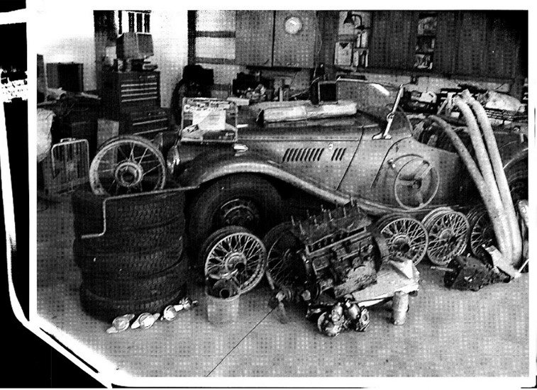
TF3006 – The start of the project…
A trailer was borrowed and in the summer of 2008 a trip was made to Ohio and the car began its journey to Calgary AB Canada to start its 13 year- long restoration. The car was dismantled in Calgary with the parts graded, bagged, marked and listed with a second list generated of “stuff” needed and a worldwide search for parts began.
After the subsequent retirement, everything was moved to Nelson BC Canada where the restoration began in earnest. Winter months were spent in Tucson Arizona (MG parts trailered down and back, for restoration/refurbishment), and summer months were back in Nelson BC with EVERY part being refurbished back to like new condition, or it was replaced. Every nut, bolt and washer was cleaned/de-rusted, re-threaded and then coated with a product called RPM, designed to prevent ferrous metal from rusting.
The frame and every body part was inspected and repaired, then prime coated with a paint called Master Series, a single stage epoxy that was designed by a chap who restores old VW Bugs and claims that once coated, prevents future rusting. There was actually little rust on body parts as the car had sat covered, in the rear of a heated garage, for some 30 plus years.
Some parts were sent out to specialists for refurbishment as follows:-
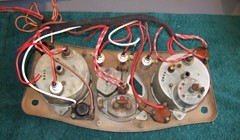
The Dash Instruments were sent to John Marks, back in England, where he did a magnificent job of restoring them to a like new condition.
The rear end gearing was changed to 4.3 to 1, done with a friend in Calgary.
The SU Fuel pump was rebuilt by the late Dave Dubois.
The Distributor was rebuilt by Jeff at Advanced Distributors.
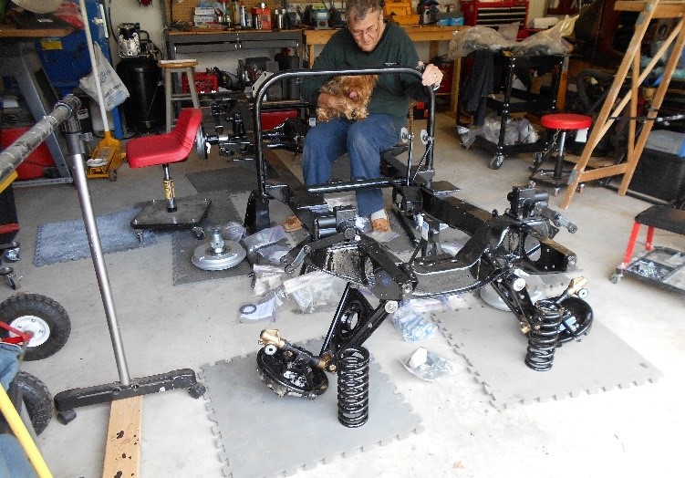
Some bits to be getting on with!…….
When purchased, the car had a wrong 1500 BMC ‘B’ series engine in it, so it was removed along with the incorrect MGA gearbox. In its place the correct XPAG was put back in, along with the correct gearbox – both of which were rebuilt using videos; the engine using the Edney video and the gearbox using the Barry Jones video. The engine got a reground crank, new main bearings, reground camshaft, refurbished valve train, new pistons, new rings, new Edney grooved tappets, pushrods, MGB fan, and a rebuilt Laystall aluminium head. The gearbox and shifter were disassembled, then rebuilt with new bearings.
The engine, gearbox, rear end/axles (including new half shafts from the late Jerry), new 48 spoke wire wheels, new old driveshaft, re-cored radiator, were now installed back onto the frame.
Good progress being made – summer of 2015.
The front axles were rebuilt and a new Moss Rack and Pinion steering gear were added also. The brake lines were replaced using the new NICOPP softer alloy and all new rubber hoses. The clutch rods installed were the new Declan Burns SS units with bearings.
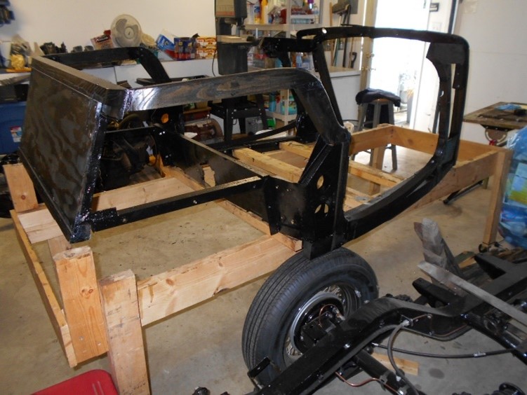
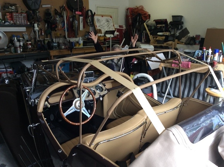
Now the tub! All the old wood was removed and replaced with a Mountain Ash kit from NC. All the inside surfaces were cleaned, rust removed, doors included, then painted with the one part, rust proof, epoxy paint and then reassembled over the new wood using non-ferrous nails and screws. A new firewall was added as the old one was chopped about to fit the wrong 1500 engine. The doors were hung using refurbished, bushed, hinges and mostly refurbished door hardware.
Above: new tub assembled from a kit – Below: door fitted.
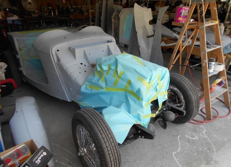
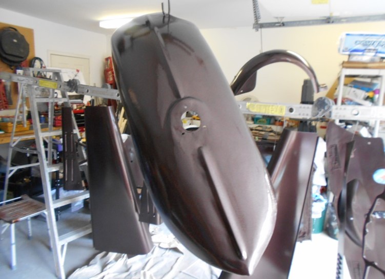
It was now time to prep for paint. The body pieces were treated to planishing hammers and good quality body filler then sanded….. What a repetitive, ugly job!!!!!! Dust over EVERYTHING! Two Part Epoxy Primer paint was then used over which a Base Coat Clear Coat two-part epoxy was sprayed using a HVLP gun. Done in the garage.
All the chromed parts were done at a shop in Tucson AZ before the shop was closed down for environmental issues.
Above: Tub and firewall in primer –and Below and Below again: paint job.
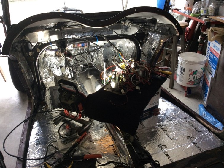
Installation of lead sound/heat insulation
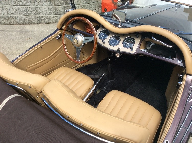
The tub was now mated to the frame using roof rubber instead of felt and the doors and tub bolts adjusted so that the doors shut clearly and crisply. The tub interior was refinished first by installing lead sound/heat insulation then using a light tan/biscuit colour vinyl, with the seats refurbished, then reupholstered, in leather, by my wife (Glenda) of 54 years.
A black carpet kit was also installed. The steering wheel and column were added. The metal dash was painted and new glove boxes added. The instruments were installed to the dash, after the clock was modified with the electronic upgrade, then loosely installed. All of the other body parts, gas tank, chrome parts, wings, windshield etc were attached. One invisible change was made to the side panels. They were “Split” per the Jim Melvin (SOCAL) design. The accessibility, for maintenance, this provides to the engine compartment, is now equal to the TD. Stone Guards, from Australia, for the rear fenders were chromed and installed.
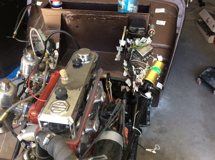
Time for the loom! The loom came from British Wiring. Every end was tinned and every wire tagged. Since the original TFs only had 2 fuses, an extra panel with 12 extra fuses was added, thanks to the design from Evan of Dayton Ohio. The Dash was re-pulled and every circuit was then completed using the correct connectors. The rear light interiors were changed to include LED circuit boards, made by Geoff Baker in Tucson. Light output is significantly better than the originals.
Dashboard and front wiring.
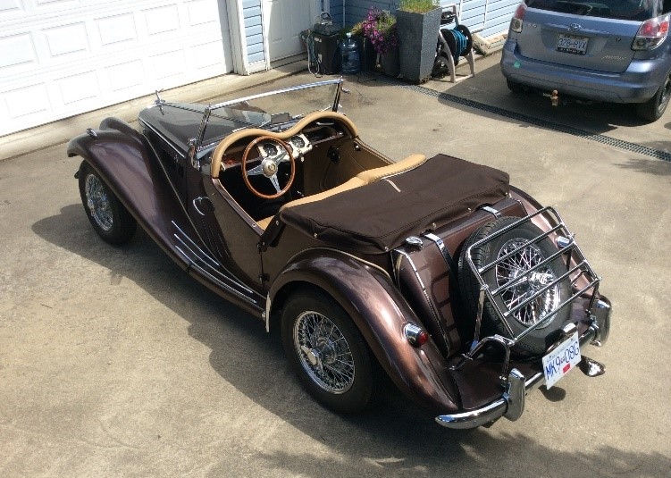
Hood and Tonneau were supplied by Don Trimming and were installed using Snaps and LTDs on the rear of the tub.
Above: Hood installation – Below: Seats refurbished then reupholstered, in leather, by Rod’s wife.
Parts for this car were procured from all over the world, using the Steve James Auctionwatchsite and without that site this restoration would still not be finished.
The two main BBS sites, MG Enthusiast, MG Experience and the TTT2 web magazine have been an absolute source of inspiration and help. Many have contributed their time and efforts to help me complete this project and I will forever be in their debt.
Suppliers like Moss, Abingdon Spares, The Little British Car Company, Brown and Gammons, John James, Tom Lange and the many individuals from whom I have received parts, have played a major role in the completion of this project.
Finally, there are two others that I would like to thank; the first is a very wonderful man, George Raham, who through this process has become a great friend. He has owned a 1950 TD that HE drove off the Sales Lot in 1951 and still has it. He more than anyone has provided parts, advice, help and kept my interest from lagging by periodically letting me drive “Black Beauty”….. The second is my wife of 54 years. She has been a second pair of hands, whenever needed, and put up with my absence into the garage and has seen the air turn “blue” too many times to recall. I am forever in her debt in her efforts to help me achieve that 10 year-old lanky kid’s T- Series dream.
On to the “Shakedown”!
Ed’s note: Brilliant story Rod and a wonderful restoration!
UK Readers may like to know that the sound/heat insulation is an Eastwood product stocked by Frost Restorers Equipment https://www.frost.co.uk
It is available as Part number 12117 “Eastwood X-mat Low Profile Sound Deadener Material Kit” (9 piece) for 129.99 GBP.
Part number 12118 is as above, but 3 pieces for 53.50 GBP.
Part number 12116 is the 1piece equivalent for 19.99 GBP.
I have been doing some research to arrive at the answer. It is not going to be accurate down to the last car, but it will be at least as good as we can get.
The research is extremely time consuming, so results will have to be published over the following two issues of TTT 2. However, the first tranche of results may give us an indication of the possible end result in terms of numbers and percentages.
The research method is to trawl the MGCC ‘T’ Register’s TA database and exclude any non-UK cars. Where a chassis number and corresponding registration number is shown, the registration number is then cross referenced to the DVLA enquiry facility and the car will be either shown as:
Taxed
Untaxed
Not taxed for road use
SORN
(or won’t be shown at all i.e. is not known to DVLA).
Some explanation of the above categories is required as follows:
SORN stands for Statutory Off Road Notification. It was introduced on 31st January 1998 to deter vehicle excise (car tax) evasion. Any car for which a SORN declaration has been made will not be on the road.
The ‘untaxed’ and ‘not taxed for road use’ categories are exempt from SORN because they were not taxed at the time of its introduction and have not been taxed since. I have written to DVLA for an explanation of the difference between the two. Any car in any of these two categories will not be on the road.
Cars in the ‘not shown’ category are not known to DVLA. It is likely that some, and possibly, quite a few exist. These are vehicles which for one reason or another were not notified by owners to the DVLA when the central vehicle record was being set up. Going back in time, it was feared that these would not be able to be registered and put on the road. However, through the good offices of the Federation of British Historic Vehicle Clubs (FBHVC) agreement has been reached with DVLA whereby classic car clubs can, by adhering to strict criteria, certify entitlement to registration as and when the cars are ready for the road (many have been lying dormant for several years and need to be re-commissioned, often by means of a full restoration). Sadly, many owners will die, leaving the car unfinished.
For the purpose of this exercise, only cars which are currently known to DVLA (whether taxed, untaxed, not taxed for road use or on SORN) have been included to arrive at an auditable figure of cars which are actually in existence. If owners have been through the process to get their car on the DVLA central computer there is a good chance that the car actually exists.
A separate listing of cars by chassis number which are not known to DVLA is included at the end of the list of cars known to DVLA in this issue of TTT 2 and will be included in subsequent lists in the December 2021 and February 2022 issues.
I need to acknowledge the help and support of Stewart Penfound in this exercise. Stewart is the Registrar of the ‘T’ Register of the MGCC for the TABC models and is dedicated to the cause of tracing these cars, wherever they may be.
In his quest to find them all, he currently has 281 TAs listed by registration number which do not appear on the MGCC ‘T’ Register’s TA database as their chassis numbers are unknown. These ‘cars’ (some may not exist) have been identified from photos, for sale advertisements, etc, etc. It is possible that this list may be whittled down as the exercise proceeds, but in any case, the list will be published at the end of the exercise.
An interesting by-product of this exercise is the DVLA information on engine cubic capacity. Whilst this information is only as good as that received by DVLA (so some information may be wrong because owners have not updated it) it should give a broad indication of the types of engine fitted e.g.
1141cc XPJM, 1250cc XPAG, 1292cc MPJG.
What follows are details in respect of chassis numbers TA0251 to TA 0987 (TA0251 not shown as it is not in the UK):
ChassisRegistration Engine On the road?
0252 CJO 617 1141 SORN
0266 DRF 575 1293 Taxed
0267 JB 9446 1345 Untaxed
0272 JB 9449 1141 N/T for road
0275 JB 9447 1141 Taxed
0276 NJ 9704 1250 Taxed
0279 CYY 800 1350 Taxed
0280 DUB 219 1124 N/T for road
0282 CAH 637 1250 Taxed
0283 CNF 4 1290 Untaxed
0291 JV 4917 1290 Taxed
0298 JB 9444 1141 Taxed
0299 BTB 670 1292 Untaxed
0302 JM 2751 1141 Untaxed
0305 JB 9842 948 Taxed
0309 CYT 610 1292 SORN
0312 BUR 754 1292 Untaxed
0314 HG 4679 1250 Taxed
0318 MG 4881 1350 N/T for road
0319 DLG 849 1250 Taxed
0335 DTN 488 1250 Taxed
0336 ADA 764 1292 Taxed
0338 312 UXE 1292 SORN
0341 DVX 402 1292 Taxed
0342 AHR 703 1141 N/T for road
0346 BKV 67 1292 Taxed
0352 MG 4950 1292 Taxed
0358 EPE 104 1250 Taxed
0360 673 MMG 1141 Taxed
0361 EPJ 338 1141 Taxed
0364 DCD 17 1292 Taxed
0366 RV 9688 1292 Untaxed
0367 CRB 539 1292 Taxed
0375 BDF 315 1000 Taxed
0381 FPB 91 1141 Untaxed
0382 YJ 4012 1292 Untaxed
0390 CKB 433 1292 Taxed
0393 MG 6303 1292 Taxed
0397 SSV 873 10 N/T for road
0404 CWE 398 1292 Taxed
0408 DCD 144 10 Taxed
0411 CFY 548 1141 Taxed
0417 CWE 399 1000 Untaxed
0418 DGH 23 1141 Taxed
0421 CBP 961 1250 Untaxed
0427 ACY 496 1141 Taxed
0428 DXD 910 1250 Untaxed
0437 ABL 67 1141 Untaxed
0439 DGY 858 1292 N/T for road
0446 JN 8235 1141 Taxed
0452 SO 5643 1141 Untaxed
0455 CHY 605 1249 Untaxed
0456 FPG 357 1141 Taxed
0457 SH 5351 1141 N/T for road
0463 JI 6976 1999 Taxed
0467 CKF 519 1300 Untaxed
0469 BTC 998 1292 Untaxed
0470 BDF 323 1292 N/T for road
0471 FPD 737 1141 Taxed
0472 CKB 526 1141 Taxed
0475 MG 4582 1292 Taxed
0481 CBP 345 1250 Taxed
0484 MSU 807 1250 SORN
0487 MG 7250 1292 Taxed
0488 MG 4851 1250 Untaxed
0489 MG 5209 1141 Untaxed
0490 KS 7221 1141 Untaxed
0492 CCV 374 1141 Taxed
0502 YXG 371 1292 Taxed
0506 CBP 536 1141 N/T for road
0507 BYD 526 1141 Taxed
0513 AWO 998 1250 Taxed
0529 SL 2352 1292 Untaxed
0532 JN 7931 1141 Taxed
0537 ARX 997 1292 SORN
0548 AJB 43 1292 Taxed
0549 ADA 796 1141 Taxed
0551 FPH 918 1141 N/T for road
0552 BVE 469 1141 Taxed
0554 EPF 290 1292 Taxed
0560 NAS 295 600 Taxed
0574 DT 8070 1250 Taxed
0578 JUM 2 1292 Taxed
0591 DGK 87 1141 Taxed
0605 DWB 124 1141 N/T for road
0607 AFS 866 1292 Taxed
0619 MG 4959 1292 Taxed
0620 AGA 383 1141 N/T for road
0622 AGA 381 1150 N/T for road
0624 BAB 938 1250 Untaxed
0632 BTC 943 1292 SORN
0633 EZ 4679 1141 Taxed
0634 MG 5605 1292 Taxed
0635 CBJ 84 1292 SORN
0645 UXS 162 1250 SORN
0654 BNP 865 1292 SORN
0655 DUG 710 1141 Untaxed
0656 CKC 605 1292 N/T for road
0664 EMX 116 1250 Untaxed
0668 EPF 487 1292 Taxed
0679 AGB 188 1250 Taxed
0682 EMK 850 1292 Taxed
0688 EPL 777 1500 N/T for road
0697 DXP 546 1292 Taxed
0717 RN 6064 1292 Taxed
0719 EPG 325 1172 N/T for road
0720 COL 771 1250 Taxed
0728 MG 5225 1250 Taxed
0729 FPA 810 1141 Untaxed
0736 EP 6633 2390 Taxed
0744 YWG 356 1250 Taxed
0746 AGB 240 1292 Taxed
0748 JU 9626 1292 Taxed
0758 358 UXM 1290 Untaxed
0774 ETW 985 1141 SORN
0777 AV 8776 1250 N/T for road
0779 DEL 973 1141 Untaxed
0783 AJU 211 1200 Taxed
0785 EHK 186 1140 Taxed
0789 IB 6797 1292 SORN
0793 BTD 804 1292 N/T for road
0797 CKF 222 980 Taxed
0799 CFY 820 1292 Taxed
0812 BAK 822 1292 Taxed
0821 BDF 906 1292 Taxed
0822 HD 6172 1250 Untaxed
0824 MG 5104 1141 Taxed
0833 DGH 173 1200 Untaxed
0844 BTG 855 998 N/T for road
0847 COM 745 1124 Taxed
0852 BDG 589 1141 N/T for road
0853 361 CYD 1498 Taxed
0856 GFO 164 1141 Untaxed
0859 BTD 806 1250 Taxed
0865 ASC 468 1290 Taxed
0873 BTD 810 1292 Taxed
0875 CON 971 1292 Taxed
0876 BAH 861 1141 Taxed
0877 EMX 212 1133 N/T for road
0878 LXS 604 1250 Untaxed
0880 ST 8907 1141 N/T for road
0881 CYD 533 1292 Taxed
0885 ELH 238 1141 Taxed
0887 AMJ 131 1292 Taxed
0905 CVO 553 1141 Taxed
0908 FPD 986 1141 Taxed
0919 MG 5307 1141 Taxed
0923 AGD 739 1292 N/T for road
0932 ABL 962 1141 Taxed
0934 ABL 964 1292 Taxed
0935 ABL 965 1292 Untaxed
0939 BCY 223 1250 Taxed
0943 DDH 900 1141 SORN
0952 233 VPK 1250 SORN
0967 EZ 5745 1296 Untaxed
0986 DUM 603 1292 Untaxed
0987 AGE 986 1295 Untaxed
The foregoing completes the listing of all known chassis numbers with their corresponding registration number from Stewart Penfound’s database, which can be identified from the DVLA enquiry facility. As previously intimated, this is ‘Part One’ of the TA listing and takes in the first 750 chassis numbers (TA0251 to TA1000). The December TTT2 will take in chassis numbers TA1001 to 2000 and the February 2022 TTT 2 will take in the remaining chassis numbers (TA2001 to TA3253).
I am not claiming that the listing accounts for every single TA in the UK (for the first 750 chassis numbers) which is live on the DVLA computer, but I would not be surprised (and I would be delighted!) if a couple more turn up.
A separate listing of TA chassis numbers with their corresponding registration number (for the first 750 chassis numbers) in respect of cars NOT known to DVLA is provided after the following brief analysis.
Of the 157 TAs listed;
87 are Taxed (55.4% of total)
57 are Untaxed or Not Taxed for road use (36.3%)
13 are on SORN (8.3% of total).
Please bear in mind that this is early days, and of the total TA production of 3003 cars, only the databases covering the first 750 cars have been interrogated (says he with a groan at the size of the task still to be completed!).
Predicting the end result for cars which are taxed and on the road is fraught with difficulty as there are a number of variables. However, I’d be disappointed with a total of less than 300 and ecstatic if the total exceeded 350. We will just have to wait and see, but the results coming out of the next analysis (chassis numbers 1001 to 2000) should enable a more accurate prediction.
The listing of cars by chassis number and registration number NOT known to DVLA which follows, will help Stewart with his records if owners come forward to confirm that their car is still in existence. The records in respect of some of these cars date right back to the 1980s and there is the possibility that some may have been scrapped (at least one TA is known to have been scrapped – not included in the listing) or exported.
TAs with chassis numbers in the 01251 to 1000 range NOT known to DVLA
Chassis number Registration number
0264 JK 6000
0270 EPC 678
0277 BRK 509
0290 CPP 736
0295 HV 7913
0321 ADA 202
0328 EPD 641
0358 WXG 492
0388 DGJ 853
0332 JB 9445
0405 ABL 39
0426 DBH 245
0478 DGF 786
0482 DUB 804
0499 DLA 676
0536 DLP 440
0569 MG 4917
0575 DKL 667
0576 DKN 915
0577 EPE 704
0609 MG 4951
0637 DYW 246
0660 UD 8580
0673 DLD 834
0680 HMV 570
0684 BFD 271
0732 RD 9263
0735 BG 4947
0742 FMC 539
0772 DWL 949
0792 ADC 374
0800 CRU 336
0801 BTD 805
0802 DLB 537
0803 DKA 75
0807 ASC 789
0869 BTD 808
0870 BTD 809
0882 ENK 850
0809 COP 684
0901 ARV 737
0902 CWJ 961
0922 BTD 811
0931 ABL 961
0933 ABL 963
0960 ABL 960
0961 BP 411
0962 DKT 839
0967 EZ 5745
0978 FPH 578
0984 DTA 761
0985 EPK 448
Please send any information regarding either of the lists to me (John James) jj(at)ttypes.org [please substitute @ for (at)]. I will pass any received on to Stewart Penfound.
Finally, a note of explanation for our non-UK readers. DVLA stands for Driver and Vehicle Licensing Agency. It is a Government Agency (not a Government Department, but similar to one) that operates the central licensing system for drivers’ licences and vehicle licences.
Vehicle registration (the licensing system) was originally operated by Local Government offices until it was centralised in 1974, with the DVLA progressively taking over this work and installing the records on to the central computer in Swansea, Wales.
Here is the tale of the little project I gave myself in the garage during lock-down.
I have owned, restored and raced TDs since my first one in 1960, and am pretty au fait with everything about these great little cars. The gearbox however is a territory I have never strayed into. It is known to be weaker than the previous TC one however. (In my full-race TD I had converted it to the unbreakable TC ‘box).
Here in France, there is much less chance to find parts or people who can fix, so I was lucky enough to obtain a ‘box locally from my friend Mike, who had just swopped out a TD ‘box for a Ford conversion before selling the car. This ‘box had been jumping out of 3rd gear, which seems to be the first sign of trouble. (My ‘box has done it a couple of times, so this fix should give me a spare for that dreaded day!
I was in no hurry, so could take lots of time considering before making any moves. But first I contacted a couple of people out there in ‘online’, in Canada and Australia, who were MG experts and who passed on to me their knowledge of the job. Without them I could never have dared tackle the task and I had dreaded the vision of little springs, ball bearings, shims, gears etc all rolling about in the ‘box, or on the floor. (Thanks Hugh, and Bob!).
If you feel the same …. courage! as the French say … “ tout est possible!! “.
– – – – – – – – The JOB – – – – – – – – – –
The job is to insert a spacer shim on the main shaft between the front of the rear bearing and its circlip. The reason for this is to prevent the gear slipping back under load and jumping out.
So, to begin….
I was lucky to find the gearbox support which I had made up decades ago, which was a great beginning. In fact, it is ESSENTIAL.
First job . . . . . . CLEAN EVERYTHING! – this took quite a while!
Next, I removed the bell housing and the extension, followed by the top cover . . . being very careful to extract the three springs and their balls. I used a fine magnet to pull the balls out – then kept those parts in a sealed container, also here remove the speedo drive gear.
The shim will be going down the middle spring hole.
I was trying to access the insides of the box without extracting all the gears and shafts if possible.
Next thing was to remove the rear casing. Remove the three selector brackets from their shafts, putting the three tapered lock screws safely into the container with the springs and balls. You can slide the casing back a bit to let them slide off. By the way, the drive flange did not need a puller and slips off easily.
The shaft is still well supported by the bearings. . . again … clean everything.
Now we come to the shim. Hugh recommended one at 18 gauge, or 1mm, but …where was I going to find such a thing? By amazing luck, I discovered several of them of differing thicknesses in my spares!! I honestly cannot remember where they come from, but the sizes are shown, and they must be available.
I was warned that I should make sure that the main shaft would stay in place when I removed the rear bearing to avoid internal parts falling into the bottom of the ‘box, so I devised four cords to the flange ….and, using a screwdriver from the inside tapped the bearing backwards … it slid fairly easily.
So, using two large screwdrivers I prised the bearing out …
To remove, I had to untie the drive flange, but because I was not pushing anything back, the shaft and gears all stayed in place … shim in and slide bearing back in.
To replace the rear casing is straightforward – BUT … you have to fit the new rear felt seal, which can be (is) tricky (mine was completely missing). It has to fit over the end of the flange and NOT get any felt caught between flange and bearing guard washer. This means that you have to fit the rear casing with the flange already in place – i.e. drive out the bearing and washer … fit the felt and replace the flange … then replace the bearing, getting a metal-to-metal contact.
Here is the internal view:
… and here we are back where we started. I did not replace bearings or other parts as this was a first, and they all seemed reasonable enough for a “spare” ‘box. I locked the flange nut up to 65 lbs torque. and the paint?… sourced in France, may, or may not be the exact shade for an early TD.
All of this will seem a bit amateur to some folks… but here in France, “amateur” probably means someone who loves what they are doing … voilà!! ERIK
In my last article on “Keeping oil in an XPAG”, I described how replacing the original cork side cover gasket with a steel one would stop the gasket distorting and blocking the breather holes. The article also described the system used in modern cars. Here, there is a connection between the crankcase and inlet manifold to help reduce the pressure in the sump. This is called Positive Crankcase Ventilation.
In this article I look at how Positive Crankcase Ventilation works and show the results of some tests using my TC. I would like to acknowledge Jim Blackwood’s article in BritishV8 on Positive Crankcase Ventilation and David Heath, Bruce Morgan and Ray White for their articles on how to fit such a system to an XPAG.
No matter how well the piston rings seal with the bore of an internal combustion engine, unburned petrol and combustion gases will escape past the rings into the sump. This is called “blow-by”. Unless removed, these gases will contaminate the lubricating oil and pressurise the sump.
The combustion gases consist mainly of nitrogen, carbon dioxide and water vapour. These combine with the crankcase oil to form a white water/oil emulsion, acids, sludge and other harmful contaminants. In addition, the escaping gases will pressurise the sump. This will blow the oil out of the engine past even the best lip seals. Less obvious is that pressure in the sump can reduce power output. The power generated by each combustion stroke depends on the pressure difference between the top and bottom of the piston. The higher the pressure in the sump, the less this pressure difference and the less power each stroke will produce.
Crankcase ventilation removes the blow-by gases to prevent these problems.
Despite first appearances, the XPAG has quite a sophisticated crankcase ventilation system, sometimes referred to as a Draught or Road Tube. This consists of two parts. The first, and most obvious is the large diameter tube that runs from the side cover down the left (or nearside) of the engine, disappearing under the bulkhead. This is the road tube.
If you examine this carefully, you will see the bottom end is bent upwards. The reason, to better angle it into the airflow underneath the car. When travelling down the road, the air passing the end of the tube creates a partial vacuum helping to “suck” the combustion gases out of the engine. It is worth checking this tube is not restricted or blocked by a build-up of oily deposits. I have seen some articles suggesting a bottle is fixed to the bottom of the road tube to collect oil. Should you do this, it will stop the airflow creating a partial vacuum.
The second part of this system is the link between the top of the rocker cover and air filter. This allows filtered, fresh air to enter the engine to flush out the combustion gases. Check the channel in the rocker box cover and hole in the air filter are clear. For those cars that have been fitted with pancake or alternative filters, another means must be provided to allow filtered air into the engine.
Pic illustrating the link between the channel (vent) in the rocker cover (red circle) and the air filter as referred to in the text above.
This breather is very important. Without it the sump would fill with blow-by gases. While the road tube will prevent the build-up of excessive pressure, without the inflow of clean air these gases will not be flushed out of the sump.
While the Road Tube system is reasonably effective, it is far from environmentally friendly. As well as the combustion gases, unburned hydrocarbons and any oil carried down the road tube are vented into the atmosphere or dropped onto the road surface.
The Positive Crankcase Ventilation system addresses this problem by recycling and burning these pollutants. Interestingly, it was first introduced during WW2, not to prevent pollution but to allow vehicles to drive through deep water without flooding the engine.
There are two different forms of Positive Crankcase ventilation system. The first recycles the gases from the sump back into the inlet manifold. Here they mix with the petrol and air and are burned in the cylinder. This is the system normally fitted to modern cars. David Heath and Bruce Morgan describe how this arrangement can be fitted to an XPAG. I refer to this as the “re-cycling system”.
The second method is to insert a small tube into the exhaust down pipe called a scavenger. This has an angled end similar to that of the Road Tube. Ray White has written an article about fitting such a system to an XPAG. I refer to this as the “exhaust pipe system”. With this system, the unburned hydrocarbons and oil are burned in the high temperature exhaust.
Components of the Positive Crankcase Ventilation system
(Please refer to the diagram when reading the following explanations).
Fresh air intake – This is normally situated on the rocker box or camshaft cover at the top of the engine. It is usually fed from the air filter or inlet manifold. Airflow is restricted by a small hole, 3/8” (375 thou) or less in diameter. 1/8” is typical. This hole restricts the fresh air flowing into the engine. The reason for this is discussed below. The hole in the TC air filter is 3/8”.
Side chamber vent– This is the connection to the crankcase. Typically, about half way down the block. On the XPAG, the existing road tube connection is ideal.
Oil catch can – When an engine is running, the lubricating oil is being sprayed out from the big end bearings to lubricate the cylinder walls and in the case of the XPAG, the camshaft. This creates a fine mist of oil droplets which can be carried into the crankcase ventilation system along with the blow-by gases and fresh air. In the crankcase ventilation system, they can mix with the water vapour in the blow-by gases forming an emulsion that blocks the flame trap or PCV valve. While not necessary, an oil catch can avoids this problem. Additionally, some oil catch cans can act as a flame trap removing the need for a separate trap.
Flame trap– There is the danger that a backfire could cause the oil mist in the sump to explode. The flame trap consists of an expansion chamber filled with wire wool to prevent this happening. It is important one is fitted and that it is regularly inspected to check it has not become blocked.
PCV valve– This is the component that controls the flow of gases from the crankcase into the inlet manifold or exhaust. It is a flow control valve that allows full flow at low pressure differentials across the valve and a metered restriction above that level. Sounds very complicated. In practice, a very simple component. It consists of a spring-loaded tapered pin that controls the gas flow through an orifice. As the pressure difference across the valve increases, the tapered pin is pushed into the orifice to reduce the gas flow. PCV valves have a non-return mechanism fitted to prevent blow back increasing pressure in the sump.
Fresh air intake & PCV valve – Working in conjunction they serve two purposes:
The PCV valve and Fresh air intake work together to control the depression, or reduction in pressure below atmospheric in the sump.
The Fresh air intake controls the volume of un-metered air entering the inlet manifold.
The volume of air that can flow through the Fresh air intake hole depends on the pressure difference across it. The greater the pressure difference, the greater the volume of air. In contrast, there is a fixed volume of gases flowing through the PCV valve, independent of pressure. Hence, the pressure in the sump drops to the point where the volume of air flowing in through the hole in the fresh air intake, plus the volume of the blow-by gases is the same as the volume of gases flowing through the PCV valve.
The smaller the hole, the lower the pressure in the sump. The engine is not designed to withstand a low pressure in the sump. For example, on the XPAG, a drop in pressure of 1 lb/in2 (about 6% of atmospheric pressure) corresponds to a large person standing on the side of the cast aluminium sump!
The second purpose of the Fresh air intake is to restrict the volume of air entering the engine. This is important for the re-cycling system. The carburettor accurately measures the volume of air flowing through it, adding a controlled volume of petrol. Air entering the inlet manifold from the positive crankcase ventilation system weakens this mixture by an uncontrolled amount. The less volume of blow-by gasses (which have no oxygen in them), the more air can flow in through the Fresh air intake and the greater the weakening of the mixture.
Modern engines are “air tight”. The oil filler cap and dip stick have seals, bearings have lip seals. The only fresh air flowing into the engine is through the Fresh air intake. This is not the case with the XPAG where air can leak in through the filler cap, dipstick and the front and rear crankshaft seals; a factor that needs to be considered.
Re-Cycling System
With a normally aspirated engine the outlet of the PCV valve is connected to the inlet manifold between the engine and throttle butterfly. When running at part throttle, there is a partial vacuum in the inlet manifold. This draws air and blow-by gases through the PCV valve.
There are two problems with this arrangement:
Un-metered air from the fresh air vent is being drawn into the inlet, weakening the mixture. The larger the hole in the Fresh air vent, the worse this problem.
Under full throttle, there will be no vacuum in the inlet manifold. This is when blow-by will be at its maximum. In this case the sump becomes pressurised and the blow-by gases are vented through both the PCV valve and Fresh air intake.
With a “blown” engine, the outlet of the PCV valve is connected to a point between the carburettor and blower where the blower creates a partial vacuum. With these installations, an oil catch can is important to prevent oil/water emulsion damaging the turbo or supercharger.
This system is not suitable for cars that are raced. In this case the engine is running on full throttle for a lot of the time.
Exhaust Pipe System
With this arrangement the outlet of the PCV valve is connected to the scavenger that is fitted into the exhaust pipe between the manifold and the silencer. The scavenger is basically a pipe with an angled end that protrudes into the exhaust pipe. As the exhaust gases flow past the end of the scavenger pipe, this creates a partial vacuum. Like the Recycling system, this vacuum draws air and blow-by gases through the PCV valve.
The main advantage of this system is that the volume of exhaust gases and vacuum increase with increasing throttle settings. Additionally, the fresh air flows into the exhaust and does not weaken the mixture.
The greatest disadvantage is the risk that the very hot exhaust gases could ignite the oil vapour in the blow-by gases creating an “explosion” in the sump.
Does the “Recycling System” Work on an XPAG?
Before fitting a Recycling system, I decided to test how effective it was at stopping oil leaks on my TC.
I have already fitted a vacuum advance and I have two 1/8” tubes connected to spacer plates between the inlet manifold and the carburettors. These provided the vacuum connection for the test. All that was then needed was an adapter to “plug” into the vent on the side cover after removing the road tube.
A separate tube provided a connection to a pressure gauge to allow the depression in the sump to be measured.
For the first set of tests, I fitted a restrictor between the air filter and rocker box cover. This had a very small 1/32” Fresh air intake hole. This was removed for the second set of tests. The next challenge was to measure how much oil was leaking. For this, I drove a 20 mile route over country roads and a section of 60 MPH dual carriage way. On return, the car was parked over a clean piece of cardboard. The number and size of the oil stains gave an indication of how effective the system had been.
Pic showing the test rig connected to the engine side cover with the pressure gauge, the Flame trap and PCV valve in position and the tube leading to the inlet side of the engine.
Findings
The temporary fitting suffered from two problems:
The two tubes connecting the PCV valve to the inlet manifold were only 1/8” diameter. Ideally the PCV valve should be connected with a 3/8” tube which has 4 times the area for the gases to flow through. This means these tubes as well as the PCV valve were restricting the flow of the blow-by gases.
I do not think the connection to the side plate was 100% gas tight, allowing air to leak into the PCV system without passing through the engine.
Both these factors reduce the possible crankcase depression.
The depression in the sump was measured by running at fast tick over (i.e. maximum vacuum in the inlet manifold), and measuring the pressure. This gave values below atmospheric of:
1/32” Fresh air intake hole – 1.75 to 2lb/sq
3/8” Fresh air intake hole – 1lb/sq in.
Had the engine been airtight, this large difference in the diameter of the Fresh air intake hole should have given a greater difference. One possible explanation was that there was a high level of blow-by. However, cylinder compression tests did not suggest this was a factor.
The cardboard “leak tests” are shown below. They look like the ink-blot tests used by psychiatrists and need some explanation.
When I stop my TC, I normally get three areas of dropped oil. Two smaller patches, one from the front seal and one from the rear seal and a larger area in the middle where the oil runs down the sump and drops off the bottom.
This is shown on the No PCV picture.
With the 1/32” Fresh air intake hole, the oil leakages from the front and rear seals appear to have gone. However, there were signs of oil leakage past the dip stick which had run down the sump and a large patch from the centre of the sump.
The probable reason for this was that the high level of depression in the sump had stopped the leakage from the front and rear seals. However, at higher throttle settings, the Fresh air intake hole and diameter of the pipes connecting to the inlet manifold were too small to allow the blow-by gases to escape. This caused the sump to pressurise, blowing oil out of the rear bearing seal and dip stick.
The second test with the 3/8” hole only showed a few drops from the front and rear seals. None from the centre of the sump. With less depression in the sump, oil is still leaking at a lower rate from the two seals. However, the larger Fresh air intake hole was able to better vent the blow-by gases at high throttle settings.
Conclusion
These tests suggest that a PCV system fitted to an XPAG is one way of keeping the oil in – particularly for engines fitted with lip seals.
For anybody considering such a modification, the steel side gasket sold by John James is recommended. There is a risk that the additional pressure difference across the original cork gasket may cause it to distort and block the breather holes.
If a Re-Cycling System is fitted, thought should be given to the size of the Fresh air intake hole. Too small and it may not be able to cope with the blow-by gases at high throttle settings or provide sufficient fresh air to flush out the blow-by gases. Too large it may not produce an adequate depression in the sump. It may also make the mixture too weak.
The ideal size of the Fresh air intake hole will depend on the “airtightness” of the engine.
The size of the Fresh air intake hole is less of a problem for anybody considering the Exhaust Pipe System.
Thought also needs to be given to sealing the oil filler cap and dipstick. If not properly sealed, these will allow un-filtered air and dirt to enter the sump. For those engines that are not fitted with lip seals on the crankshaft, there is a small risk that in-flowing air could carry dirt into the seals causing excessive wear.
For the record, these tests were run with a FV237 PCV valve on an XPAG that is not fitted with lip seals.
Paul Ireland
Ed’s note: Reference was made earlier to Ray White’s article in Issue 64, which described the “exhaust pipe system”. Ray has since posted the following comment to his article, which may not have been seen by many of you. It has since been edited by me (without altering the sense of the original comment):
I have to say I had something of a quiet panic when I read Paul’s article (having received advance notice of it) because Paul has described how he believes the rocker box to air filter pipe connection works. He says that “fresh air” is drawn into the engine from the air filter. I have always understood the system worked the other way around; in that the carburettor sucks out the fumes from the top of the engine and recycles them with fresh air via the filter – into the combustion chamber and out of the exhaust. This would assist in crankcase ventilation when the vehicle is stationary and the draught tube is inactive.
My point is that if the system works as Paul describes then my crankcase ventilation system (which relies on the exhaust drawing the fumes out of the top of the engine through this pipe) may not work. Having said that, however, this system is essentially the same as one fitted to a TF that has been working fine in the USA for some time.
Ed’s further note: Paul has commented as follows:
In practice what Ray says about “I have always understood the system worked the other way round;” is “sort of” true.
I did not bring this point out in the article as it, a) is only a minor effect and, b) complicated to describe.
No matter how the crankcase is ventilated (Road tube or PCV), there are two “holes” through which the blow-by gases can escape. The fresh air intake in the air filter and the vent tube.
Which route the gases take is only dependent on pressure difference. If there is a lower pressure in the road tube (or PCV) than in the engine, this will draw the blow-by gases out of the engine. If the “residual” pressure in the engine is, then less than that in the air filter. Air will flow from the air filter into the engine. This would be the “normal” operation when driving along the road, unless there is an excessively high blow-by due to wear.
If the residual pressure in the sump is greater than in the air filter, the blow-by gases will flow into the air filter.
The clue that this is not happening is that normally the free air intake is free of excessive oil. This suggests air is flowing INTO the engine rather than OUT OF in which case it would carry the oil from the rocker box.
The next question is “what is the normal pressure in the air filter”? This is a difficult question because it depends on the efficiency of the filter and the air flow through it (or throttle setting). At low throttle settings it will be at or very nearly at atmospheric pressure. This means that when the car is stopped at tick over, with a PCV system, there is a low pressure on the vent tube and nearly atmospheric on the air filter so all the blow-by gases will vent via the vent tube. With a road tube system, I suspect the majority of blow-by gases will vent via the vent tube (it is atmospheric pressure with a large diameter “hole”) and yes some will vent via the air filter as it is at a slightly lower pressure but only connected via a small hole.
At high throttle or full throttle, the picture is different. There is a large airflow through the air filter and there will be a pressure drop, although this is small. With a “recycling” PVC system, the vent tube will be at virtually the same pressure as the air filter (in practice it will be slightly lower due to air friction in the carburettor, etc. So, the situation will be very similar to that described for the road tube at tick over. For the road tube, the vent will be at a lower pressure due to the movement of the car and the original comment will apply where the flow depends on the residual pressure difference.
The American cars use a slightly different system to manage the case of full throttle running, however, I will not go into that here.
As I said, I did not include this in the article as I feel it makes it very complicated. Please let me know if you think I should include more detail.
Ed: I think we will leave it there for the time being!
To some readers this may seem OTT – and I understand that – but I have never felt confident that the oil pump will not, on occasion, be starved. The earlier XPAG engines as fitted to the TC had, for some reason, the oil pick-up on the left side of the sump. I suspected that this could result in temporary oil starvation – on hard left-hand bends, for example – so to avoid the possibility of this ever happening, I have fitted additional baffles to the sump. Incidentally, I have read about oil starvation on road cars, so it’s not just limited to racing.
(I understand that later engines had the oil pick up centralised – which must have been done for a reason.)
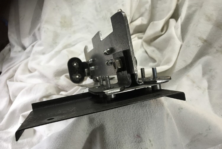
In my sump, there is a small baffle to the front which, in the original design, was presumably intended to reduce forward oil surge under braking. I have retained this but added further baffles, which I believe will help prevent starvation to the oil pick up and also reduce splash.
Here the front baffle is removed and shows how my addition was first fixed. The four substantial brackets provide a good surface area and are an interference fit with the sump walls. However, it didn’t stay like this as a design change was called for.
During the rebuild of my TC I have endeavoured to make any modifications fully reversible and to that end I resisted the temptation to drill or weld the sump.
At this early stage I had thought a small gap under my new baffle would be sufficient for oil equalisation but, again, as the project evolved, I had other ideas…
In the following picture the small baffle has been returned to its normal position where it also serves to prevent the new one from climbing upwards. I understand later XPAG engines had an extended horizontal baffle, so my plan was to also add one; the aim being to reduce the amount of oil being splashed up. Obviously, a certain amount of lubrication is required… but too much can inundate the bores and overwhelm the piston oil control rings.
First, I cut a suitable piece from plate steel and shaped it to fit the profile of the sump. I then made two openings as shown and carefully measured and drilled 8 x 5mm holes. I then measured and drilled 8 more holes in 2 x ‘one way’ flaps that I made from some steel hinges. I have chosen to secure the flaps to the vertical baffle with slot head screws and ’Nylock’ nuts – which I believe are capable of withstanding engine temperatures at sump level. The flaps will move easily; with the oil holding them closed when needed (on left hand bends) and open in all other situations.
A lip on the edge of the original horizontal baffle created a gap between it and my additional one. I overcame that problem by repositioning the two front brackets (turned through 90 degrees) and using them with distance pieces to enable four bolts to hold it in place.
… as shown in the photo, I used four small round distance pieces and the two brackets to enable all three baffles to be bolted together.
The last photo shows the sump with everything bolted in place. I deliberately left a gap at the side so sufficient oil can splash up to the bores.
As I say, this may seem OTT for a road car… …but I enjoyed doing it. Ray White
Ed’s note: For the benefit of some of our readers for whom English is not their first language, ‘OTT’ stands for “over the top”. You could say it means “more than is really necessary.”
To obtain the best results from the horn some consideration must be given to its mounting, and great care must be taken to ensure that it is securely clamped to some substantial member of the vehicle. Details of design vary so considerably that it is impossible to recommend one particular part on which the horn can be mounted.
HF1234 horns are designed for external mounting, whilst HF1235 horns are designed for under-bonnet mounting.
In whatever position the horn is mounted, care must be taken to clamp it firmly and to ensure that there is no possibility of it fouling the engine or fittings through vibration when on the road.
WIRING
Before making any alterations to the wiring, disconnect the battery lead, or if a battery master switch is fitted, switch to the off position to avoid the possibility of short circuits. On vehicles fitted with Lucas combined cut-out and voltage regulator units, a convenient battery supply point is terminal A2 on the control box or fuse unit.
All leads should be kept as short as possible and securely clamped in position. Do not clamp cables against sharp edges where there is a danger of abrasion through vibration. Avoid taking cables round acute bends or where that can be splashed by oil or water.
The cable to be used must be of adequate size to carry the horn current, which is 4 amps for 12 volt horns and 6 amps for 6 volt horns.
Prepare a length of cable of adequate current carrying capacity to connect between the battery supply point and one of the horn terminals. The other terminal on the horn should be connected to one terminal of the horn-push. Normally the horn-push on the vehicle will already have cables connected to it and the lead from the horn should be joined to one of these at a suitable point. If the horn-push is not earthed internally, the other terminal on the push must be connected to a good earthing point on the vehicle chassis.
MAINTENANCE
Before being passed out of the Works, the horn is adjusted to give its best performance, and will give a long period of service without any alteration. If the horn fails, or becomes uncertain in its action, first ascertain that the trouble is not due to some outside source, e.g. a loose connection or short circuit in the wiring of the horn. Ensure that the horn terminals are fully tightened. It is also possible that the performance of the horn may be impaired by the fixing bolts working loose.
If, after carrying out the above examination, the trouble is not rectified, the horn may need adjustment, but this should not be necessary until the hons have been in service for a long period. Adjustment does not alter the pitch of the note; it merely takes up wear of moving parts.
ADJUSTMENT OF HORNS
Correct adjustment of the horn requires the use of a D.C. ammeter (0-10 amps. scale) in series with the horn under test.
The correct current consumption should be:
6 volt model … 6 amps
12 volt model … 4 amps
To adjust, operate the horn push and turn the contact breaker adjustment screw (Fig.1) in an anticlockwise direction until the horn just ceases to sound. Then turn the serrated adjustment screw clockwise six notches (a quarter of a turn) and check the performance and current consumption. Further adjustment should be made by turning the adjustment screw one ‘notch’ at a time in a clockwise direction and re-checking, until the best performance is obtained with current consumption not exceeding the values quoted.
Fig. 1. Rear view of horn.
If a suitable ammeter is not available, the following procedure can be adopted if the horn note is considered to have deteriorated: –
Operate the horn push and turn the adjustment screw anticlockwise until the horn just ceases to sound. Release the horn-push and turn the adjustment screw clockwise for six ‘notches’, when the original performance should be restored.
Finally, if the note is still unsatisfactory, do not dismantle the horn, but return it to a Lucas Service Depot or Agent for examination.
JOSEPH LUCAS LTD BIRMINGHAM ENGLAND
Editor’s note: The Lucas Altette model HF 1234 was fitted to the TC, certainly the later TC, as it quotes this model number in my copy of ‘Lucas Equipment’ for the 1949 TC.
I’m not sure of the source of these instructions, but I have re-typed them because the print size in the original document was rather small.
Russell Dade contributed a fine article entitled Altette Soundings which covered the restoration of an Altette model HF1234 in Issue 56 (October 2019) of TTT 2.
Here’s his finished example:
Any mention of horns and some of us immediately think of ‘Taff the Horn’ (Taff Isaac down in South Wales). I’m not sure if Taff is still around (I hope he is) but there is a message on his website www.taffthehorns.com that “TAFFS PARTS NOW BEING TAKEN OVER BY terrybinns1957(at)gmail.com”.
Firstly, apologies for some problems which resulted in me getting Issues 66 and 67 mixed up. I’m told that if you download Issue 66 (June 2021) from the archive, the front cover incorrectly states that it is Issue 67 (August 2021) – the rest of the issue is correct. I will get this changed as soon as possible – if only I could do it myself, but “you can’t teach an old dog new tricks!”
The last couple of months have been extremely busy for me as most of my energies have been channeled in the direction of my J2. I’m pleased to say that it fired up at the end of August, thanks in no small measure to the efforts of Adrian Moore and his team at Finishing Touch bodyshop in Weston-Super-Mare. You might find it hard to believe that the last time the engine ran was when England won the World Cup in 1966!
By the time this issue reaches you, Pre-War Prescott will have been held. It was originally due to take place on 15th July, but was postponed to 11th September due to Covid. It would have been nice to have taken the J2, but I wanted to iron out a few ‘bugs’ and stay relatively close to home for the time being. We should be able to venture further afield in 2022.
It’s sad to report the passing of Graham Robson on 6th August aged 85. Graham was a prolific writer of motoring books (169 of his books were published) and he was still busy writing right up to the time of his death.
Some more sad news to report is the deteriorating health of Dennis Barker, a former Chairman of the MGCC ‘T’ Register. Dennis went into a Care Home a few weeks ago.
This rather splendid TC is being offered for sale by Mark Whitchurch. It is TC2190, registration number DNJ 137. Restored in the late 1980s, it was re-commissioned in 2016/2021. The car has an extensive history file, including original buff log book, previous ownership details and what has been done in the restoration and re-commissioning.
Documented less than 800 miles since its full restoration. In good mechanical and cosmetic condition with some lovely patina. 27,000 GBP or near offer. mark.g.whitchurch(at)gmail.com [substitute @ for (at)]
Maurie Prior from New South Wales, Australia, has sent me the following comments about classic car values in Australia:
“I noted in your editorial, your comments over the declining/static values of Northern Hemisphere T-Types and found that there are significant differences “Down Under” to the Northern Hemisphere prices. Here in Australia, several MG T Types, and particularly, TFs have been sold in these last twelve months and not surprisingly, they have achieved never-before-seen prices. Another even more surprising factor is availability – at present, there are no TFs of either engine size for sale anywhere in Australia that I am aware of!
Just last month, in July, a nicely presented, matching numbers TF1500 was sold for almost $70,000 AUD, a record, and was sold within three days of being offered! Quite a few cars that have been put up for sale have sold quite quickly and at prices that were never even considered a year ago! The average sale price seems to be hovering about the high $40s mid $50s with concours quality cars off the planet!
I believe that there is a simple reason for this – we Australians are intrepid travellers, and due no doubt to the tyranny of distance, we tend to travel further than most, and as a consequence stay away longer. To this end there is much more holiday money spent than the average world traveller, given the cost of getting to and from. Since we have closed our international borders, there is no international travel, so our cashed-up travellers are not only travelling extensively internally, but also are spending up on everything from home renovations, holiday homes, works of art, and classic cars! So, there are some benefits from Covid-19 here in Oz – instead of spending our hard earned in the ‘Old Dart’, Europe and the Americas, we are spending it at home, and helping our battered economy. I hope it may forever continue – the spend-up not the virus!”
This website uses cookies to improve your experience. We'll assume you're ok with this, but you can opt-out if you wish. Cookie settingsACCEPT
Privacy & Cookies Policy
Privacy Overview
This website uses cookies to improve your experience while you navigate through the website. Out of these cookies, the cookies that are categorized as necessary are stored on your browser as they are essential for the working of basic functionalities of the website. We also use third-party cookies that help us analyze and understand how you use this website. These cookies will be stored in your browser only with your consent. You also have the option to opt-out of these cookies. But opting out of some of these cookies may have an effect on your browsing experience.
Necessary cookies are absolutely essential for the website to function properly. This category only includes cookies that ensures basic functionalities and security features of the website. These cookies do not store any personal information.
Any cookies that may not be particularly necessary for the website to function and is used specifically to collect user personal data via analytics, ads, other embedded contents are termed as non-necessary cookies. It is mandatory to procure user consent prior to running these cookies on your website.