Category Archives: Issue 42 (June 2017)

The Editor

Welcome to Issue 42, June 2017!

“Petrol cars will vanish in eight years says US report”. This was the front-page headline of the Daily Telegraph Business section (Monday, 15th May issue).

The article quoted the source document Rethinking Transportation 2020-2030, authored by Stanford university economist Tony Seba.

The demise of the internal combustion engine is based on the premise that people will stop driving altogether and will switch en masse to self-drive electric vehicles. It is said that these are ten times cheaper to run than fossil-based cars with a near-zero marginal cost of fuel and an expected lifespan of 1 million miles.

We would be wise not to dismiss this forecast out of hand. One only has to look back at the pace of technological advances over the past twenty-five years or so to conclude that it is quite plausible.

Mopping the sweat from my brow, I continued reading and was heartened to read that “Only nostalgics will cling to the old habit of car ownership.” “Nostalgics?” that’s us! Oh, good! but my sense of relief was tempered by the message in the next paragraph which talked of banning cars powered by fossil fuels from the cities, then to the suburbs and then beyond. Sacré bleu!

I then took a cold shower to pretend that I had not read any of this and immersed myself in the details of an e-mail from Peter Cole about the 2017 TTT 2 Tour. According to Peter and Vanessa, we look set to have 45 cars booked in at the hotel with up to another 5 cars joining us on the day trips, crewed by owners in the local area.

The following is the content of Peter’s e-mail:

“The routes so far are as follows:

On Saturday, we head to the east of Chichester with a coffee stop at Bignor Roman Palace, then it’s north Loxwood on the Wey and Arun Canal. From there on there are several pubs to choose from for lunch.

After that it’s west towards Haselmere and south again to Midhurst. At Midhurst there are lots of opportunities for a late lunch including the farm shop at Cowdrey Park. From Midhurst there is a choice of either heading directly back to the Weald and Downlands Living Museum at Singleton where we have been invited to join their Vintage and Steam show, or to take a more circuitous route towards South Harting. Click here to see

At the museum, we will have a designated parking spot. From there it’s just a short drive back to the hotel for our Gala dinner; through Goodwood, past the horse racing track, the motor racing circuit and the Rolls Royce factory. The journey distance is 65 – 70 miles.

The Sunday route is still work in progress but we will head west towards Rowlands Castle, after which we are looking at visiting the Victorian brickworks at Bursledon for coffee followed by a trip to Stansted Park Click here to see where we can we can take a late lunch in the Victorian conservatory, ride on the light gauge railway or visit their garden centre. Again, we will have designated parking in front of the house”. 

If this whets your appetite and you have not yet booked to come on the tour, there are still some rooms left at the hotel (we reserved 50 rooms). However, it’s best to check with Peter and Vanessa first (01243 267234).

The MG Owners Club has once again invited over John Twist, who founded University Motors in the US in 1975, to present two one-day seminars in October. We are jointly supporting the second of the one-day seminars (the event in Coventry) with the MG Octagon Car Club.

The following details have been received from Richard Monk, General Manager:

“Following the success of last year’s John Twist Seminars at the MGOC Workshop in Swavesey we are delighted to announce that the renowned MG expert will return this October offering his wisdom and insights over two weekends and at two separate UK venues.

Over the weekend of 14th _ 15th October John will present two one-day seminars at the MGOC Workshop in Swavesey; the first is entitled The Complete MGB Tune-Up; the second The Complete MG Lubrication. While over a long weekend 20th – 21st – 22nd October, John will be based at Wroxall Abbey Hotel near Coventry where he will offer three distinct Tune Up seminars on pre-61 MGs featuring the MG Magnette on Friday 20th, the MGA on Saturday 20th and the T-series MGs on Sunday 21st.

The cost of attending a one-day seminar at either location will be £90 which includes a light lunch and refreshments.

Further information about the seminars and booking is available via the link on the MGOC website.”

The next issue of TTT 2 will include a pen picture of John, who has totally involved himself in the world of MGs for more years than he cares to remember.

Just enough space to mention that Dr Christian Bianco is again running the MGs in the Dolomites event from 28th September 2017 to 3rd October 2017. The first part will be based in Sottoguda (BL) in the Italian Dolomites, the second will take place in Hergiswil/Switzerland. Your UK contact is Gary McCarroll 01604 404939. Closing date is 30th May.

JOHN JAMES

DISCLAIMER BY THE EDITOR

Totally T-Type 2

is produced totally on a voluntary basis and is available on the website www.ttypes.org on a totally FREE basis. Its primary purpose is to help T-Type owners through articles of a technical nature and point them in the direction of recommended service and spares suppliers. Articles are published in good faith but I cannot accept responsibility or legal liability and in respect of contents, liability is expressly disclaimed.


MG TC Brake Improvement

For some time now I have been pondering how I can improve the poor braking of my MG TC.

Of course, it is possible to convert the existing set-up to a twin-leading shoe arrangement, but that would entail surgery to the backplates and I was reluctant to undertake this if another solution could be found.

After an inspection of the front brakes, I observed that the two eccentric adjusters of the brake shoes just began to engage at 3/4 from the beginning, although the brake linings were still quite new (5 mm thick)!


So, the brake cylinders had quite a long way to go before braking……


From a piece of steel (2 mm thick) I made 2 little U-turns and bolted them to the front brake shoes, where the brake-cylinders push them to the drums. (see pictures). Did this only on the front drums, because the brake power is about 2/3 at the front, and 1/3 at the rear.

For the stops of the adjusters I made a narrow ring (from a mounting piece of IKEA cupboard I still had in my possession…..) – see previous picture.

After searching on the Internet I found a firm in Alkmaar called “Leeuwenkamp Van Langen Techniek bv” (www.remmenservice.nl), who sell special brake linings for ‘oldtimers’. Normally, the friction-coefficient of our brake linings is about 0.20, but they have a Ferodo DS 3920 brake lining with about 0.42 friction-coefficient. Thickness 5 mm. Often used in karting and F1.

The material is bonded to the brake shoe, and then adjusted to the drum.

When mounting the brake shoes I put some chalk on them. After turning the wheels sometime, took them off again, and then the places are clearly visible where to sandpaper. Do this again, till there are no visible spots at last. Also brake sometimes in between to settle the shoes. Of course: don’t forget to put on the drum first!

Well, the braking result is sensational! With reasonable power on the brake pedals the car stops immediately. Even just braking using the handbrake is sufficient to stop at once!
Of course in the future there should be more wear on the brake linings, but with the 1500 miles driving per year I don’t have to worry much. It is also nice feeling the break-pedal in a higher position.

Hope you will all benefit from this!

Frans Sitton
My e-mail: mgtf1954(at)zeelandnet.nl {Please substitute (@) for (at)}.

Ed’s note: I checked a few details with Frans as follows:

I wanted to know how the narrow ring (courtesy of IKEA) was fitted to the stops on the brake shoe. Frans explained that:

“The narrow (IKEA) ring fitted just very tight. Had to mount it between my vice. The inside hole is drilled with 8 mm. Outside measures 11 mm, and the depth is 6 mm.”

I also wanted to check that the Ferodo linings were also fitted to the rear drums (this seemed self-evident from the increased efficiency of the handbrake), but I thought I had better check. Frans confirmed this.

Lastly, I made some enquiries about the availability of Ferodo DS 3920 in the UK and conclude that it should be readily available.

Friction Services (a couple of miles from my house) stock this brake lining material https://www.frictionservicesltd.co.uk/index.php/vintage__classic_automotive-intage__classic_automotive/?k=22370:2

and will bond it to the shoes. It is done in various thicknesses but 5mm is stocked. As the original lining thickness is 3/16 inch (4.7625 mm.) a fair amount of sanding down would be required.

TB0362 GNA 175

TB0362 graced the front cover of February’s issue (Issue 40). I promised in the April issue that I would reproduce some of the photos of the rebuild that owner, Sergio Pagano sent me, along with a few more pictures taken by the professional photographer, Daniele Bilotto from Marano Principato (Cosenza) – Italy.

Following the publication of Issue 40, Bill Hentzen from Wisconsin contacted me with some history of the car. Bill has been involved with Tickfords for many years and recalls visiting the Cooke Group in Wigston, Leicestershire in 1987 with the late Ian Lloyd to see TB0362. The car had just been fitted with a new body.

Bill’s records of the car go back to the mid-1970s when it was owned by one Jacob Potts as a pile of bits. From a letter in 1975 from Mr Potts, it appears that the first years of the car were spent in Cheshire and the war years at RAF Predannack* on Cornwall’s Lizard Peninsula. It then languished until Potts rescued the derelict car. He worked on the chassis but the body was beyond salvation, which is almost certainly when the Cooke Group acquired it and constructed a replacement.

(*Nowadays, the runways are operated by the Royal Navy and it is used as a satellite airfield and relief landing ground for nearby Royal Navy Air Station Culdrose.)

Ownership passed to Robin Lawton Classic Cars, Hampshire and Sergio purchased the Tickford in December 2011 in the UK, following the Bonhams auction in September 2011. Unfortunately, the car was badly damaged on the ferry across the Channel whilst on its way to Italy and needed considerable repair to the body, bonnet and hood.

Sergio has added some comments on the rebuild and some ‘Thank you’s’ as follows:

Five long years of work and study to know how to rebuild it correctly and a lot of nights to find solutions to difficult problems, such as the adhesive foil that I designed for the dashboard. This gave me a lot of satisfaction, in fact, I supply it still, all over the world, to help T-Series owners to rebuild in a cheaper way the dashboard. Personally, I would not have done all this, without the help of:

– Bill Hentzen (Wisconsin – USA) for his valuable suggestions

– Peter Radcliffe (Hull UK) to supply rare Tickford spare parts, including the hood. Especially for the 10 days that he spent at my house in April 2016 to definitely finish the car.

– Paul Banyard (NTG Motor Services Limited) for the supply of TB items, for his patience and his warm welcome when I have been to his shop in Ipswich.

My thanks to all of them.

Ed’s note: The adhesive foil for the dashboard centre panel was featured in a previous issue of TTT 2. I’ve reproduced later in this article some photos of Sergio’s work showing the ‘before and after’ centre panel.

If you are interested and wish to contact him, his e-mail address is sergio.pagano61(at)gmail.com {please substitute @ for (at)}.

Now for some photos………..

TB0362 as purchased in December 2011.

Restoration of the chassis – February 2015.

Restored front wings.

Restored rear wing.

Sergio checking detail after painting.

This ‘shot’ taken after painting.

View from inside prior to fitting out.

View of dashboard wiring.

Peter Ratcliffe checking hood frame.

Hood lining fitted.

Getting there!

Sergio and Peter.

Sergio’s centre panel before work.

Entire sheet in self-adhesive black with the words printed in white.

The completed centre panel after work.

And to close…. A couple more photos taken by photographer, Daniele Bilotto from Marano Principato (Cosenza) – Italy.

Suck, Squeeze, Bang and Blow – the Manchester XPAG Tests

Ask an MG owner how their petrol engine works and the answer you are likely to get is ‘suck, squeeze, bang and blow’. If only matters were that simple! Before presenting the next set of data from the Manchester tests, this article introduces some of the concepts affecting the combustion of fuel in a 4-stroke spark ignition engine. It describes the journey taken by a single cylinder in an XPAG engine running at 3000 rpm where it completes the four stages of the cycle in a mere 40 thousandth of a second (40ms). Think how fast 1 second is and imagine that 1ms was equivalent to 1 second. On that timescale, 1 hour would last 6 weeks! 1ms is so fast that even gases can act like solids.

Suck

Suck timeline

The start of our journey is where the piston is at top dead centre (TDC). At this point you might expect the exhaust valve to close and the inlet valve to suddenly open. Valves cannot open and close instantaneously and any delay as the inlet valve opens reduces engine power. Fortunately, MG engineers knew the valves could start to open earlier and close later than expected, increasing an engine’s power. At the start of our journey, the inlet valve will already have been opening for 0.6ms (11O before TDC) and it is another 1.3ms (24O after TDC) before the exhaust valve fully closes.

The 1.9ms when both valves are open is called valve overlap and is beneficial at higher RPM. At the top of the “blow” stroke the piston has expelled most of the exhaust gases and as the inlet valve starts to open, a “scavenge” effect takes place where the rush of gases into the exhaust port draws in some air petrol mixture through the inlet valve.

At TDC the cylinder is not empty. The 45.5cc volume of the combustion chamber (about 15% of the 312.5cc cylinder volume) still contains hot exhaust gases at approximately 1200oC left over from the previous cycle. As the piston starts to fall, the exhaust gases will continue to vent through the exhaust valve, and the remainder will cool as they expand. (If you ever studied Physics, you may remember Boyle’s Law. As a gas is expanded it cools, and when compressed it gets hotter). At some time between TDC and Bottom Dead Centre (BDC) when the pressure in the cylinder becomes lower than the inlet manifold pressure, the air petrol mixture will start to flow in earnest into the cylinder. Induction has begun.

The volume of mixture entering the cylinder is controlled by the throttle butterfly. This is a circular brass plate that pivots when the throttle is pressed, allowing more mixture to flow into the engine. As the throttle is opened, the suction piston in the carburettor responds, moving upwards as more air flows through the carburettor. Its height is a measure of the volume of air flowing into the engine and by withdrawing the tapered needle from the jet, it allows more fuel into the air stream.

In this way, the SU carburettor is able to accurately control the air / fuel ratio.

The ideal mixture for the inducted air/fuel is a stoichiometric ratio consisting of 14.7 times the mass of air to petrol. Unfortunately, carburettors are volumetric devices; they deliver measured volumes of petrol and air. The addition of ethanol, currently up to 5%, affects the ideal stoichiometric ratio. Ethanol contains oxygen, whereas petrol does not. With ethanol blended fuels you need more fuel and less air, i.e. a richer mixture. Fortunately, SU carburettors can be adjusted to accommodate for this effect. This will be covered in a later article.

Depending on throttle setting and engine revs, around 10% of the petrol will evaporate in the carburettor cooling it. In normal road use when the engine is probably running at part throttle, this will not be noticeable. However, for racers who want the maximum power output it reduces the volume of petrol entering the engine and hence maximum power. This cooling can also cause carburettor icing, probably more likely in engines with exposed carburettors such as motor bikes. Modern fuels have a greater range of light fractions to improve cold starting that are more likely to evaporate in the carburettor. In addition, ethanol requires twice the heat to evaporate as petrol. All this contributes to increasing the cooling effect. If you are suffering from carburettor icing, this will get worse as the percentage of ethanol increases. The solution would be to use a fuel with a lower percentage of front end components as described in the previous article.

The inducted air / petrol mixture consists of 20% oxygen (O2), 80% nitrogen (N2) and small quantities of other atmospheric gases, some of the petrol as vapour and the remaining as varying sizes of liquid droplets. At low revs or light throttle settings, petrol may be deposited on the inlet manifold walls, an effect called pooling, before it streams into the cylinder.

The first air petrol mixture entering the cylinder meets the residual hot exhaust gases. These heat the incoming mixture and cause some of the droplets of petrol to evaporate, cooling the residual gases in the process. Before the petrol can burn it must be a vapour. To achieve the ideal stoichiometric mixture all the liquid petrol entering the cylinder must boil before ignition and be mixed with the air. This boiling is unlike what you see in your kettle, where bubbles form in the bulk of the liquid. Inside the cylinder the petrol evaporates molecule by molecule from the surface of the droplets. The small droplets with a large surface area relative to their volume will evaporate the fastest. Even though the residual gases are extremely hot, they will not contain sufficient energy to evaporate all the inducted petrol.
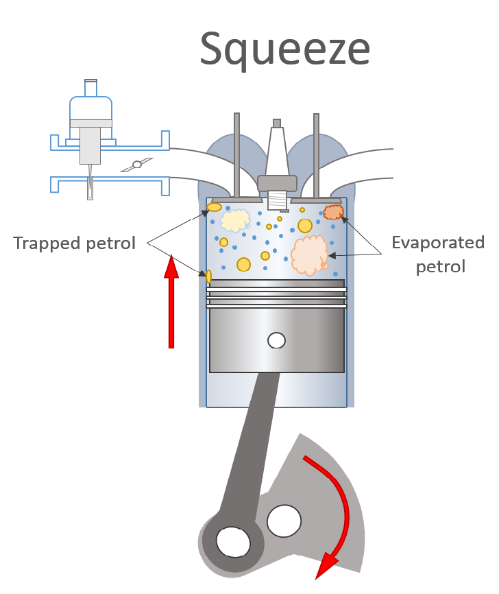
Squeeze

Squeeze timeline

After reaching bottom dead centre (BDC), the piston starts to rise, however, Induction continues for another 3.2ms (57O after BCD) until the inlet valve closes. During this time, the air petrol mixture entering the cylinder 90mm above the piston does not feel the effect of the piston’s upward motion and continues to flow into the cylinder. This increases the cylinder pressure about 0.2 to 0.5 lbs/inch2 above that of the inlet manifold and is called the stagnation pressure. The compression stroke does not start in earnest until the inlet valve has closed and continues for another 6.8ms until the piston reaches TDC, after 20ms, or halfway into our journey.

During this compression stroke, the pressure and temperature of the mixture increases, providing heat to evaporate more liquid petrol.

Pockets of rich and weak mixture will form as the liquid petrol evaporates. Turbulence in the gasses will mix these with the air in the cylinder as the compression stroke progresses.

Like many modern designs, the combustion chamber in the cylinder head of the XPAG is boat shaped. As the piston approaches the top of the stroke, the gasses on the outside edge of the cylinder, where the cylinder head overlaps the bore, are “squished” into the combustion chamber, increasing turbulence and mixing.

At the end of the compression stroke, liquid petrol may still be present in the cylinder, trapped between the piston and cylinder wall, around the valves, or as large droplets of fuel that have not evaporated. This may be more common in low compression engines where there is less compressive heating. Even if the carburettor is delivering the correct mixture, the presence of liquid petrol at the end of the squeeze stroke will result in a weak mixture when the plug fires. This will have a significant impact on the growth of the flame front.

Bang

Bang timeline

Combustion is initiated by an electrical spark in the gap of the spark plug.

There are products on the market that increase the power of the spark and claim to also improve the engine’s power or efficiency. This was one effect that was investigated at Manchester by measuring engine’s full throttle power output as a function of spark energy at 2000, 2500 and 3000 rpm.

The graph shows that the energy in the spark has no effect on power output over the range of RPM investigated. This is hardly surprising when you consider the chemical energy released by the small volume of petrol ignited by the spark is over 1,000 times that of the electrical energy in the spark! As long as a spark is formed, no matter how weak, the combustion process will start.

The only benefit of systems to improve the spark energy is to reduce misfiring caused by dirt or defects in the high tension components of the ignition system. Unfortunately, even these high energy systems will fail to deliver a spark to the plug if the condition of the ignition system is very poor. It is important to ensure the distributor cap, rotor arm, coil, plug caps and plug leads are mechanically sound (no scratches or burns from arcing) and are clean and free from dirt and moisture. This will ensure even the standard ignition system will perform to the optimum.

The flash point of a flammable liquid is the lowest temperature at which there is sufficient vapour for an ignition source, such as the spark plug, to ignite the mixture; its auto-ignition temperature is the lowest temperature at which it will spontaneously ignite, burning without a source of ignition.

Auto-ignition is bad as it causes the pressure in the cylinder to rapidly increase, resulting in pinking or knocking. An ideal fuel has a low flash point and high auto-ignition temperature.

After the spark plug fires, there are three phases during the combustion cycle. Firstly, a fireball of burning mixture about the size of a pin head is created. This fireball grows as the flame front moves outward at approximately 35cm/sec depending on the pressure in the cylinder and air / fuel mixture around the spark plug. This initial phase of the combustion is slow and a significant factor in the time taken to burn the fuel. Furthermore, a weak or rich mixture around the plug will significantly slow the growth of this initial fireball, leading to a late cycle. Once the fireball has grown to approximately the size of a pea, the second phase begins when turbulence takes over and spreads these ignition points throughout the volume of the cylinder, rapidly igniting the remaining mixture.

When petrol burns in the presence of sufficient air, the hydrocarbon chains break down. The hydrogen (H) combines with the oxygen (O2) in the air to produce water (H2O) and the carbon (C) combines with the O2 to produce carbon dioxide (CO2), liberating a great deal of energy in the form of heat, 33 million joules for each litre of petrol. During the third stage, this heat both evaporates and burns any remaining liquid fuel and dramatically increases the pressure of the gases in the cylinder.

After ignition, the ideal situation is that the pressure in the cylinder will reach its maximum 17o after TDC (0.8ms after TDC), anything different and the engine will not produce as much power.

It takes a relatively long time from the spark that creates the initial fireball to all the mixture being burned. As revs increase it is necessary to advance

when the spark plug fires to provide sufficient time for all the fuel to burn before the optimum. On very early cars this was achieved manually, typically by a lever on the steering wheel. On later cars and the majority of MGs, this is done by bob weights in the distributor which fly out as engine revs increase, causing the ignition timing to advance.

The graph below compares the “centrifugal” advance curve for the XPAG from the Manchester tests (green) to the original curve from a rebuilt TC distributor (red). The original advance curve is around 5o too retarded below 4000rpm, supporting general observations that it is necessary to advance engines when using modern fuel. Unfortunately, the shape of the original curve is wrong. Increasing the standard advance to 5o static, improves the timing up to ~3000rpm, beyond which the engine is too advanced.

The growth of the initial fireball is also dependent on the pressure in the cylinder which, in turn, is related to throttle setting. At light throttle settings, cylinder pressure is low and the growth of the flame front slower. More advance in addition to the centrifugal advance is needed. On later cars, this is achieved using the vacuum pod on the distributor which is connected to the inlet manifold. A light throttle setting reduces the pressure in the inlet manifold, causing the pod to advance the ignition timing. Earlier cars do not have a vacuum advance.

At Manchester, vacuum gauges were connected to a plate fitted between the carburettor and inlet manifold. This allowed the vacuum advance to be measured during the part throttle tests, shown in the graph below. At light throttle settings, up to an additional 15 degrees advance must be added to the centrifugal advance to obtain the correct timing.

Once the ignition has fired, a race starts between the pressure waves caused by the flame front rushing across and down the cylinder and the piston moving upwards. At 30o advanced, the piston still has 8.5 mm to travel (9.3% of the stroke) before it reaches TDC. During this time, the building pressure is working against it. As pressure builds, so does the speed of the flame front, resulting in a rapidly increasing cylinder pressure.

Maintaining the correct advance is important. Running an engine too advanced will result in damage to the piston and big ends as the building pressure tries to force the piston back down the cylinder, reducing the power output. Running too retarded leads to an increase in exhaust temperature, burned exhaust valves and damage to the cylinder head. Both these effects were investigated at Manchester by measuring the full throttle power output as a function of advance.

What is interesting is the insensitivity of power output to ignition timing. At 3000rpm, advancing or retarding the ignition by as much as 10-15 degrees only changed the power output by ~5%. This suggests the combustion profile is very spread as is discussed below.

The change in exhaust temperature with ignition timing is more pronounced.

After ignition, minor variations in the turbulence, and particularly the mixture around the spark plug, can have a significant effect on the growth of the initial fireball lead to an effect called cyclic variability. If you were able to measure the crank angle when the maximum cylinder pressure was reached and count the number of cycles that occurred at that angle, you would get a frequency plot as shown in the example below. The orange curve corresponds to low cyclic variability and the blue and dotted blue curves to higher cyclic variability.

Unfortunately, measuring the timing at which the peak pressure occurs in a running engine requires specialist equipment, not available for the Manchester XPAG tests. The effects of cyclic variability, however, can be assessed by comparing measurements using different fuels, or in this case, different ignition advance settings to assess its impact. Future articles will describe how carburettor settings or different fuels can reduce cyclic variability.

The effect of cyclic variability is to broaden frequency curve, shown by the blue and dotted blue curves. As the magnitude of the cyclic variability increases, fewer cycles occur in the maximum power range, decreasing the engine’s power output. Additionally, there are a small number of cycles where peak pressure occurs before TDC, these cycles pink – an effect referred to as “micro pinking” by John Saunders when he investigated the effects of modern fuel. Cycles where the peak pressure occurs late in the cycle will have insufficient time to fully burn and will still be burning when the exhaust valve opens, increasing the exhaust temperature.

Advancing the timing moves the curve to the left, as shown by the dotted curve. Slightly increasing the number of cycles that will pink and significantly decreasing the number that are burning late in the cycle, reducing the exhaust temperature. When the timing of the peak pressure is spread by cyclic variability, ignition timing makes little difference to the number cycles in the maximum power band (shown in blue). Power output is very insensitive to advance.

The data clearly demonstrates these two effects, indicating cyclic variability is a significant factor during the Bang cycle of the XPAG engine.

Cyclic variability explains some of the myths surrounding modern fuel. The measurements show an average reduction in exhaust temperature of around 20oC for each 5 degrees advance. The standard advance curve for the XPAG is 5 degrees too retarded, which increases exhaust temperature by 20oC, explaining why some people think modern fuel “burns hotter” even though actual combustion temperatures are unchanged. Furthermore, the increased number of late burning cycles gives the impression that modern fuel burns more slowly, when it does not.

These findings highlight the importance of us using the correct advance curve for an engine, both to avoid micro-pinking, and keep the exhaust gasses as cool as possible. A suggestion would be for each of the registers to sponsor rolling road tests on “typical” cars to measure and share the centrifugal and vacuum advance curves.

Mechanical distributors deliver a timing accuracy of around +/- 2 degrees, increasing the width of the curve above. These should be checked for wear, sticking bob weights, and to ensure the vacuum advance is working properly. Electronic distributors are more accurate. Programmable ones allow the advance curves to be accurately set.

I have now fitted a programmable electronic distributor with a vacuum advance to my TC. This is programmed using the curves measured above. The net result is a significantly advanced ignition timing above the standard, particularly at low throttle settings and as predicted by the tests, my car runs noticeably cooler particularly in slow moving traffic.

Unfortunately, the power stroke ends all too quickly 7.1ms after TDC when the exhaust valve starts to open (52o before BDC) and the high pressure gases rush out of the cylinder in a process called “blowdown”. Blowdown utilises the remaining combustion pressure to “get the gas in the exhaust moving”. Without this effect, energy would be lost during the exhaust stroke as the piston would have to push the gases out of the cylinder.

The piston is powering the car forward for just 18% of the time of each cycle.

Blow

Blow timeline

If everything were perfect, a fully combusted mixture of gases consisting of water vapour, carbon dioxide and nitrogen rushes into the exhaust, expanding and cooling to around 500oC. The piston reaches BDC, 2.9ms after the exhaust valve started to open and as it rises the remaining exhaust gas is pushed out of the cylinder.

Combustion is not perfect; petrol vapour requires oxygen to burn. The droplets of petrol that evaporate during the combustion cycle will initially exist as “vapour droplets”. Although the temperature is sufficiently high to cause these to burn, the absence of oxygen means they will not burn properly, appearing in the exhaust as unburned hydrocarbons or carbon monoxide. Turbulence will mix these pockets of partially burned fuel with oxygen, allowing them to fully burn as the gasses leave the cylinder and travel down the exhaust, further increasing exhaust temperature.

A gas analyser looking at the exhaust gases reveals a great deal about the combustion process. The un-burned hydrocarbons show how much petrol has been unable to burn in the cylinder or exhaust due to a lack of oxygen. This can arise either because of a rich mixture, or poor combustion as described above. Finally, NOX or Nitrous Oxide, (NO) is produced at high combustion temperatures when the nitrogen in the air oxidises. NOX is bad for three reasons. It takes energy from the burning hydrocarbons, further reducing the engine’s efficiency; it reduces the amount of oxygen available for the fuel to burn and it is an atmospheric pollutant that contributes to ‘acid rain’. The presence of NOX is usually an indication of high ignition temperatures caused by a weak mixture.

What about modern cars? While the valve and ignition timing will differ slightly from an XPAG, the journey described above is very similar with three major differences. Firstly, the fuel is injected as very small and evenly sized droplets, typically 50 micrometers diameter (about 1/5th the size of those produce by a carburettor). These not only mix with the air more effectively, caused in part by the careful design of the inlet manifold, they evaporate five times faster. Ultimately, this creates a more evenly distributed mixture of air and petrol vapour in the cylinder before the ignition fires. Secondly, compression ratios are higher than in classic cars, increasing the compressive heating. Finally, the timing of the spark is continuously adjusted to ensure that the mixture burns optimally, and it is typically far less advanced than for the XPAG. The race between the piston and flame front is shorter and no longer left to chance. These differences allow modern cars to run on fuels that have a wide range of different hydrocarbons.

After 40ms our journey ends, only to start over again. Each cylinder completes the cycle described above 25 times per second. Driving along in an MG TC at 3000 rpm (48 mph in top gear) this sequence repeats itself 6000 times in the four cylinders every minute. The wonders of suck, squeeze, bang and blow!

Paul Ireland

Paul says “More to come. Next one will be on carburation.” (Ed.)

Ed’s note: Talking of the sequence, which repeats itself 6000 times in the four cylinders every minute, Ron Ward has asked me to advertise the following:

“I have in build a 1350cc lightened and balanced Stage II unleaded, lip sealed, 8 inch clutch, fast road cam TD/TF engine.

Future build of same specification TC, TD and TF engines and ‘one off’ same specification sleeved to 1500cc, either TC, TD or TF.

Call Ron Ward 01422 823649”

(If you experience any difficulty in contacting Ron, please phone the Editor on 0117 986 4224 or e-mail him via the website contact form.)


Front Cover: TF2680 – 155 UYS

This 1954 TF1250 is only for sale due to the owner recently being told that he has a terminal illness.

Purchased in 2004 by him as a restoration project, he has spent the last 12 years (car completed in 2016) on a total rebuild of the vehicle.

Built as a RHD car for export, the Heritage Certificate shows it went to ‘K’ (believed Kenya).

A matching numbers example, it somehow made its way from Kenya to The Netherlands in 1964, where it seems to have sat in a barn, in the ownership of the same family, for quite a few of those years.

From inspection when it arrived in the UK, the car appeared to have been basically unmolested. It had been given a light respray over the original paintwork and even the original seat covers were found under the replacement covers.

A complete photographic record of the rebuild shows that the car was taken down to the chassis (chassis blasted) and was given a bare metal respray. Everything has been professionally rebuilt from the engine (crankshaft reground and Brown & Gammons seals fitted) through to rear axle, suspension, carburettors, instruments, etc. The gearbox was rebuilt by Classic and Sports Cars Essex, https://www.classicandsportscarsessex.com (Jason Waller and his father) who come highly recommended by the owner.

The original body tub has been retained, with the addition of new main sills and hinge posts. 90% of the original chrome has been kept and re-chromed. This obviously includes the bumpers where it is advantageous to restore the Factory fitments rather than use after-market items.

Shows attention to detail with the perfect fit of the bonnet.

The finished car was MoT’d by Brown & Gammons last year and is still being run-in. The owner says that it drives beautifully, a joy to drive, (especially now that the gearbox has been rebuilt) and has been described elsewhere as being “just as one could imagine it was like to drive one when new.”

Ed’s note: Whilst I have not seen the car I think from the photos and the description that this is as near as you would get to a new car! The car is located in the Norwich area and offers are invited around £34,000.

It is insured with Hagerty International for £40,000, agreed value.

If you are interested, please contact me in the first instance (I have no pecuniary interest in this matter).

I can be contacted by telephone (0117 986 4224) or by e-mail on jj(at)ttypes.org {Please substitute @ for (at)}.

King Pins and Bearings

Have a read of Brian Rainbow’s article in issue 9 December 2011. I followed his advice and fitted Torrington bearings to my TA2446. I then had to get the right shims to recover the float to 4 to 6 thou. I used one additional Torrington shim and then had a gap of 12 thou on one side and 16 on the other. I had bought a set of steel shim sheets, so I cut some bits out and clamped them between the old brass thrust washers and filed a pair of annular shims from 8 thou and 12 thou pieces.

My main issue was that the king-pins on my TA were not a sliding fit in the bushes, they were rock solid, plus there were some very dodgy cotter pins. I removed the cotter pins with a hammer and drove the king-pins out as well. I bought a set of king- pins from Amsteer and cotters from Roger Furneaux. Points here are, if you speak to John Davis from Vintage and Collectors Spares, he will advise that the original bushes had steel backings and brass faces. The new ones are just brass. Also, the original king-pins had an oil gallery in the centre of the pin. Finally, Roger’s cotters are easier to fit and remove without a hammer.

The pictures show how to ream the bushes to get the correct fit. I have just reamed the existing ones on the car, I still have the new set on the shelf. So, apologies for no advice or experience on replacing the bushes. They appeared to have been replaced with the addition of some less than standard thrust washers.

This is a picture of the reamer and pilot guide in use. Just ream from either end. I used 3 in 1 oil to lubricate the cutter.

My main problem was finding an expanding reamer for non-ferrous metal with a pilot guide of the correct size. I got the last one from a supplier in Edinburgh but it came with an incorrect collar. Mick Pay very kindly made me the correct one for a donation to Cancer Research. The size is 18.25mm to 19.84 mm. 19.05mm is ¾ inch so the range spans the kingpin diameter.

When using the reamer, make microscopic adjustments and test for fit between cuts. There is only a slight adjustment between too tight and too large. If you take too large a cut you will get a rippled finish with straight cut reamers, compared to the spiral ones so again make small adjustments.

This sliding collar floats on the pilot rod and the taper needs to be pushed up to the end of the opposite bush to centre the reamer.

As did Brian, I got a large gap (25 +15 thou) and thus excessive float on the king pin with the standard brass thrust washers, so I headed for the Torrington ones.

Once you have got the axle apart there are a variety of options for reassembling the components.

Points to note:

Stub Axles are marked LH and RH. The axles are threaded so that when the wheel rolls forward it tightens the nut. Left-hand side is a left-hand thread and the Right-hand side is a right-hand thread.

The axle itself has an identity cast into it and this lettering should face the rear of the car. Do not trust this and check the geometry of the king pin holes. There is a series of seven existing articles on steering by Eric Worpe that are essential reading. Check the castor angle to confirm the orientation. Put a rod in the axle and the king pin leans back at the top. Same logic as a supermarket trolley that the wheels will align to where you point it. This picture is from Eric’s article.

Fitting and removing the cotters: Do not hit them with a hammer before you are completely satisfied that they do not need to be removed in the near future. Eric Worpe recommends seating them with a hammer – “they should be hammered home and only then should the nut be tightened”. Roger Furneaux advises against. Eric’s article explains his point of view so I hit mine lightly.

Roger Furneaux’s have nuts both ends. One end of Roger’s cotter provides the steering stop at the rear, the other a means for removal. Picture of the steering stop below. Note also the slight downward angle on the stub axle.

The nut at the rear of the cotter and the one on the swivel form the steering lock stop.

The nut at the front is used for removal. Take the nut off and put some washers underneath and then tighten it back down. This has the effect of withdrawing the cotter. Keep adding washers until it comes free. Makes sure the cotter can pass through the washers! A sharp tap from the rear may start it once there is some tension on it.

Yes, I do have the only available pilot reamer but I have learnt to my cost that loaned tools invariably do not get returned. I could not find anywhere to get the work done and I was lucky to be able to purchase the tool and do it myself.

If you want your king-pins re-bushed and reamed and the stub axles crack-detected, then I can arrange the work for you with a local engineering company in Stroud who at present have my engine.

I purchased a pair of swivel/stub axles from Tim Patchett on the basis that I had crack detected my originals with no cracks, but I was dismayed at the quality of the machining on the radius of the originals and there were many machining marks that could propagate fatigue cracks.

I bought a set of bushes and kingpins from Amsteer. I also had a set of 1950s kingpins from John Davis. The 1950s ones are slightly larger than the Amsteer ones so I have used the smaller ones.

I pulled the bushes in with washers, a flat plate and a threaded rod. I did not need to take the old ones out but would have used a small socket as a plunger and a large one as a receptacle and pulled them out with a smaller threaded rod as the one I have does not go through a 3/8 inch socket drive.

You can pull the bush in from the outer end, but I pulled it from the middle to avoid any possibility of distortion.

Tim Parrott
tp(at)tpss.co.uk

Ed’s note: The seven articles by Eric Worpe, mentioned by Tim are as follows:

CHASSIS – is it true? – Issue 19 (August 2013)

FRONT AXLE GEOMETRY – Issue 20 (October 2013)

FRONT SPRINGS – Issue 21 (December 2013)

KING PINS – Issue 22 (February 2014)

TRACK ROD AND DRAG LINK ENDSIssue 23 (April 2014)

TYRES AND TRACKINGIssue 25 (August 2014)

THE BISHOPS CAM STEERING BOX – Issue 26 (October 2014)

An inexpensive hazard warning system and turn switch for any MG

TTT2 issue 13 Aug 2012 featured a panel which I constructed from parts from my deep spares bin to incorporate turn signal switches, a low oil pressure warning lamp and a buzzer. My TA has a loom with turn signals wiring and all lamps are LED. The system had limitations; the pull on push off left and right switches for turn signals were not very practical and the buzzer I used and the operating turn signals unit were not loud enough. (An electronic LED unit is normally silent in operation; units purposely made with a loud tick are available).

As an update, I have made another panel with hazard switch, turn switch, low oil pressure warning and a louder buzzer. This is screwed to the bottom of the inner dashboard.

The hazard warning switch is based on a Durite switch 00-484-50 which is push on push off with an illuminated red triangle. It has seven 6mm spade terminals, if required, a removable base is available.

The turn signals switch has three positions with the middle position as off as shown in the dashboard image, unfortunately not self-cancelling. The type of turn signals flasher unit used depends on whether LED or tungsten lamps are fitted. The tungsten lamps version works when the lamps load is applied to the flasher unit and some LED or electronic version run continuously if its 12v supply is present. The latter types are polarity sensitive. Some LED relays have no earth connection.

In the diagram in black ink the basic hazard warning switch circuit for LED lamps negative earth is shown. The circuit connects to a turn signals unit, to the left and right indicators lamps wiring on the vehicle, to a buzzer if required, and to an indicators ‘on’ lamp. A 12v feed via the ignition system and a 12v battery feed are used to enable hazard switch operation when the ignition is off. I am using the green 30mph lamp as a dashboard turn indicator as my TA speedometer does not have an outlet. Also, bright green LEDs are fed from Left and Right contacts on the turn switch located the top left and right of the turn switch via diodes for isolation. The series resistors used are 47K ohms for the green LEDs.

If a turn switch is added the additional wiring is in green. A flasher unit for tungsten lamps has a fairly loud tick but the electronic version is silent. A special electronic flasher unit with a loud tick is available. If a buzzer is used, further additional wiring is shown in red, the diodes prevent interaction. In this circuit the buzzer sounds when the turn signals are used but not when the hazard warning is operated.

For positive earth cars the diodes are reversed, the connections to the wired in left and right green LED indicators are reversed. The low oil pressure LED warning lamp connections are reversed. The buzzer connections are marked + and -. For LED vehicle indicator lamps, diodes rated at 1 amp are required and for filament lamps the rating is 4 amps. The correct polarity LED flasher unit should be used for the vehicle earth polarity.

The oil pressure switch is as described in TTT2 issue 13. As this switch (SW1) is open for no oil pressure and closes as the pressure rises, a transistor is used to effectively change this state to operate the lamp and buzzer when the pressure is low. The transistor type for the oil pressure circuit depends on the vehicle earth polarity, for -ve earth a TIP122 or similar npn transistor is used. For +ve earth TIP127 or similar pnp. Circuits for both are shown (in blue).

Hazard switch, Durite 00-484-50. £5.51 plus VAT and postage from AGM Component Solutions Ltd. www.agmpartscomponents.co.uk

Base for hazard switch if required, connectors, wiring and buzzer from Vehicle Wiring Products 01159305454 www.vehicleproducts.co.uk

The three position rotary selector switch with knob Item ID 151819788748 from eBay.

Also, transistors and diodes from eBay.

Indicators switches, positive and negative earth flashing indicators units, LED bulbs all bases, and buzzer units from: www.dynamoregulatorconversions.com

Bob Butson

Any enquiries via email to: email(at)robbut.plus.com {Please substitute @ for (at)}

TCs Forever – More! – Book Launch

Mike Sherrell sent me some photos of his book launch in Perth which was held on 7th May.

According to Mike, the weather was absolutely perfect; a cloudless blue sky, no wind, 29 deg.C and this was 3 weeks before winter!

He recalled Noel Semmens telling the audience when opening the book launch of TCs Forever! back in January 1991…. “Of course, we all know God drives a TC”. Well, thought Mike, someone must have been smiling down for this second book launch!

His eldest son Dan pulled everything together and with his partner Julie, and his sisters Jess and Em, ran the event like clockwork. There was champagne on arrival and food aplenty. Master of Ceremonies was TC Owners Club President, Colin Dines with Barry Palmer, Speaker. Both did Mike proud. His reply followed.

Mike was moved to see seven of his old restorations out front and his own two inside. Reflecting on his work over the years he said…..”Doing one at a time year in year out, they all become a bit of a blur, but to see so many together even I am amazed. I need to get a life!”

Mike looking rather pleased in the company of those “wonderful touring time machines”.

A formidable collection of (mostly) TCs at the launch.

Barry Palmer giving the address at the book launch.

Mike replying.

Mike with Master of Ceremonies, TC Owners Club President, Colin Dines.

Copies available from John James, 85 Bath Road, Keynsham, BRISTOL BS31 1SR. £60 plus £4 postage (UK) £14 (EU) £19 (ROW). Cheques payable to THE MG ‘T’ SOCIETY LIMITED, Bank Transfer to Acct no. 33458268 Sort code 77-73-11 or PayPal to paypal’at’ttypes.org

Lost and Found

Not very much to report in this issue.

Paul Harris noticed the contribution from Roger Roodhouse in Issue 41 regarding the log book he has for TC4313 and wondered if he could put in an appeal (slim he acknowledges) that somebody out there may have at least one of the old green or brown log books for his 1938 TA, FKE 423 (TA2414).

The car had one owner in Kent for over 50 years until he sold it to a dealer a few years back. The log book in question was with the car then, but sadly FKE 423 seems to have had quite a few owners in a short time and when Paul bought the car back in 2014, the log book was not with the other papers.

So, it must still be somewhere, but enquiries made of the recent owners that Paul has been able to contact all seem to have drawn a blank. Paul can be contacted at prharris25(at)aol.com {please substitute @ for (at)}.

TC0285

Philip Badger is researching the history of TC0285, seen here at The Rob Roy Hill Climb in Victoria.

Philip’s request for information was published in MG Enthusiast in August 2014, with a brief follow up plea in July 2016.

The car would have been fairly distinctive, with its black and blue speckled vinyl seats and probably some competition history with its crank-case /conrod repair and a planed near side brake backing plate – lost a wheel at some stage ???—-but no one so far seems to remember it.

Philip can be contacted at pdbadger(at)bigpond.com {please substitute @ for (at)}.

MG 6746

Peter Lansdown (Triple-M owner) has been in touch to say that he has met a previous owner of TA Tickford MG 6746. This owner is keen to know of the car’s whereabouts, if is it still around.

MG 6746 does not show up on the DVLA website.

It was owned by one Jock Manby-Colgrave in the 1940s but nothing has been heard of it since.