
Roger Wilson has written a comprehensive article on the infamous engine leak at the rear of the block in the May 2010 edition of Totally T-Type. This excellent article prompted me to look at a spare ‘Gold Seal’ reconditioned engine block, which has revealed an additional problem and also paved the way for trying out an old remedy. In this article, the term ‘oil scroll housing’ is used to describe that part of the ‘main bearing cap’ that surrounds the oil scroll on the crankshaft.
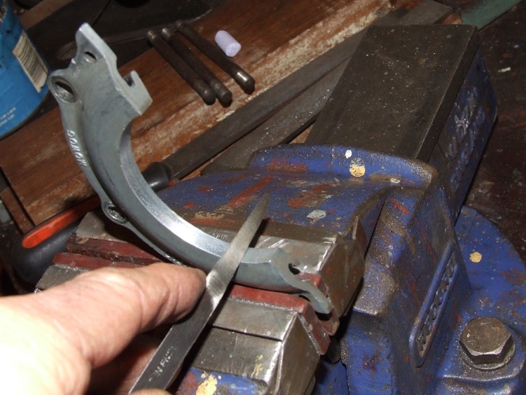
The first step was to make up the setting gauge (photo 1) detailed by Roger in the September 2010 edition of TTT.

Photo 1 – The setting gauge.
This revealed that Roger may have been optimistic when he suggested that “the oil scroll housing on the rear main bearing cap will have a uniform clearance all round, as it was bored in line with all the main bearing housings”. In this particular block I measured 0.006” clearance on one side, gradually diminishing to less than 0.001” on the other side (photo 2).
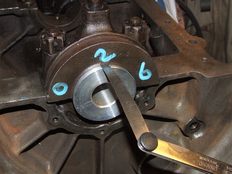
Photo 2 – checking the clearances.
My first thought was that the setting gauge was not seating properly, so to eliminate the gauge, the rear main bearing cap was mounted on a dividing head secured on a mill table and a Dial Test Indicator mounted in the chuck was then used to check the concentricity between the oil scroll housing and the shell bearing housing (photo 3). This confirmed the 0.006” misalignment.

Photo 3 – confirming the 0.006 misalignment.
A magnified inspection of the oil scroll housing’s surface suggested that some rubbing against the crankshaft’s oil scroll had taken place. This leads me to believe that wear in the main bearings could have been considerable, thus allowing the crank’s oil scroll to contact the housing; but why double the wear on one side compared with the wear on the bottom of the shell bearing? This might be explained by the tendency of a rotating shaft to climb up the bearing’s side. The location of the excess wear on the near side of the engine seems to support such an idea. Two other possible explanations exist according to a recent comment by Lawrie Alexander; wear could be due to the crankshaft main journals being ground off centre, or the engine has been line bored during a rebuild.

Photo 4 – machining the oil scroll housing.
Rather than have the main bearing cap line bored, I chose to machine the oil scroll housing to be concentric with the bearing housing (photo 4) and set up an increased uniform gap of between 0.01” and 0.015”. The object of this slightly alarming approach was to make use of a suggestion by the late Ray Sales, some 25 years ago.
He ensured concentricity between the crank’s oil scroll and the housing by wrapping a single layer of sellotape around the crank’s oil scroll and spreading a thin layer of JB Weld on the oil scroll housing. The crank, bearings and bearing housings are then assembled, torqued down and the JB Weld allowed to harden.
On dismantling, the sellotape is removed along with any excess JB Weld. Such an approach should set up a truly concentric gap of about 0.002” (0.05mm). The extra clearance machined on the oil scroll’s housing allows a thicker, more robust layer of JB Weld and to improve adhesion, a groove was also machined into the scroll’s housing (photo 5) with a slitting saw.
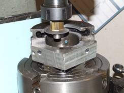
Photo 5 – machining the groove.
The slinger cap or oil thrower is the die cast Mazac cover plate that sits directly above the crankshaft’s oil scroll and is meant to be located by two 4mm dowel pins and secured by three M6 screws to the engine block. The dowel pins had been removed, perhaps confirming Roger’s comment about the Morris Engine Division (responsible for the Gold Seal reconditioned engines) having to remove the pins to help correct any misalignment. Using the gauge, a gap of 0.004” at the top of the slinger cap and a tight fit at the sides was revealed, suggesting a new cap had been installed. A light skim of the cap’s flat edge on some 320 wet and dry (photo 6) and some judicious scraping (photo 7) set up a uniform 0.002” clearance with the gauge. As Roger has advised, some semi-hardening sealant either side of the gasket would help fix the cap’s location in the absence of the pins, once the cap has been secured by its three screws. The use of some 0.002” shim steel wrapped around the gauge would help true the fixing of the slinger cap to the block.

Photo 6 (above) – skimming the cap’s flat edge and Photo 7 (below) – scraping the cap’s surface.
All the above procedures should secure a uniform 0.002” clearance around the crank’s scroll, and whilst some slight leakage may occur, a well set up oil scroll system should be inherently effective.
My conclusions support Roger’s suggestion that the oil slinger’s dowel pins are not always able to set up the correct clearance and some individual adjustment is needed with the aid of a setting gauge. Although the scroll housing should be concentric with the bearing housing, excessive bearing wear can result in increased leakage as the crank’s scroll abrades away the scroll’s housing. This can be rectified by expensive line boring or by reducing the clearance with a film of JB Weld. For good adhesion of this film to the housing, some care in preparation is needed, such as the use of a “Dremmel” to grind away and roughen up the surface.
If main bearing wear can result in abrasion between the crank’s oil scroll and the housing, then the crank’s oil scroll diameter needs to be checked and the setting gauge dimension modified to be compatible.
When assembling the shell bearings, the ends should slightly protrude by a few thou. above the housing. This allows a slight degree of “bearing crush” to take place when the housing is torqued down.
I hope this article will give encouragement and the reassurance that paying attention to detail, although time consuming, is worthwhile.
Eric Worpe
Ed’s note: This article originally appeared in Issue 5 (April 2011) and has recently been updated by Eric.
Following the article in Issue 62 (October 2020) a number of comments were posted on the website at the end of the article. Some printed copy subscribers who have Internet access might have seen these, but printed copy subscribers who do not have it certainly won’t. It’s also the case with Internet ‘subscribers’ that unless they make a point of visiting the website from time to time and going to the article, they will not be aware of the comments. Therefore, the seven comments are printed below in date order as received.
David B Smith – 8th October:
When the need arose to change the oil seal after 12,000 miles, we did it without removing the engine (TF) and made up 2 legs bolted to the lower bell housing to take the weight of the engine on the chassis rails after removing the gearbox. The original conversion had included a Speedisleeve. The motivation for the seal replacement was not the drip, which was no worse than that from most XPAG engines, but incipient clutch slip and the planned trip to the Isle of Man. The clutch slip was found to have been caused by oil seeping past the heads of the 4 bolts holding the flywheel then running along the gearbox first motion shaft and centrifuging onto the front face of the clutch plate. Lockdown happened the day after the job completed and IOM trip cancelled so haven’t done enough miles to know yet whether the new seal is successful. I was fortunate in being able to use an old-fashioned lift belonging to my local friendly garage.
Sorry am not able to show a picture in this reply.
Lawrie Alexander – 8th October:
The Moss Motors seal kit sold in the USA (p/n 433-421) comes with 9 pages of illustrated instructions and – most importantly – a seal retainer centering tool. Engines which have been line-bored sometimes move the axis of the crankshaft to one side so using the original mounting holes for the bolts that secure the upper half of the retainer locates the seal sideways relative to the crankshaft flange. One engine I worked on (before developing the seal centering tool) had the seal flattened on one side of the crank and not touching the other side! The latest iteration of the 433-421 kit has resulted in a 90% success rate: no oil leaks after installation. The other 10% appear to be the result of crankshafts being reground off-center so that the rear flange actually oscillates. This makes the seal less than efficient (and probably messes up the engine’s balance with the flywheel oscillating, too).
Trevor Short – 10th October:
Eric, I have fitted a Moss seal to my TD. The first one (ptfe type) started leaking after about 200k. On inspection, the seal had a considerable warp in it and I suspect it had been damaged in transit to Australia. I searched for a replacement, but not available in Australia. A new seal arrived from England and it checked out ok. I was a little concerned about the way the PTFE seal is fitted. All the suppliers with this type of seal supply a fitting sleeve, none is supplied by Moss. So, I machined up< a fitting adapter so the seal went on without any manipulation (Moss fitting instructions say – avoid seal puckering). Due to the seal failing I then looked at what I actually purchased. The clearances are at a premium, I think the flywheel location sleeve ended up at about 35 thou. – enough but just enough. I follow you on the PTFE seal 1. they can run dry 2. they can run in oil. Due to the 3/16 return hole they will run in a reservoir of oil due to the height above the seal. And yes, why don’t they now with the PTFE seal incorporate the old scroll seal? If ever the PTFE seal fails, at least the pool of oil under the car will be tolerable until time is available to repair. The pool of oil of the seal failure was about 12 inches in diameter.
David B Smith – 14th October:
I cut the bottom off a PET drinks bottle and used that to fit the seal over the flange.
Eric Worpe – 15th October:
Thanks to the above for their interesting comments. The issue about alignment of the oil seal housing and the crankshaft could be resolved if the housing incorporated the counter oil scroll as provided by the Mazac casting. You’ll be delighted to know that I hope to submit a short post script on the oil seal housing if John allows it.
Michael Balahutrak – 22nd October:
I have just installed the seal and not enough run time to fully evaluate – BUT – in anticipation of flooding the seal area with oil and possibly creating a positive pressure in this area – I have drilled two additional holes -one each side of the drain hole to facilitate rapid pressure alleviation and oil draining – hope this will do the trick.
Eric Worpe – 22nd October:
Hi Michael, You may have a good point! I’ve wondered if drilling the drain hole at an angle, such that the spin direction of the crankshaft’s flange would encourage oil to be swept down the drain hole. The hole’s opening could also be made funnel shaped to offer a greater catchment area. I hope all this homespun theory thinking is treatable.
Ed’s note: As a follow up to Eric’s post of 15th October, he has sent in the following:
“John James managed to obtain one of the currently available oil seal housings for inspection, enabling us to confirm the absence of a counter scroll surface to the crank-shaft’s Archimedes oil scroll, as originally provided by the semi-circular Mazak die-casting, photo 1. Instead, the new housing was machined to leave a gap of some 60 thou. tapering up to a gap of 300 thou.; clearly unable to limit any oil escaping from the crank-case.

Photo 1 – comparison between original oil slinger and new housing.
This seems a lost chance to reduce overloading of the new oil seal system due to oil spray from worn main bearings. A worn engine can also result in a positive pressurized crank-case due to “blowby” past the piston rings, adding to the “load” placed on the oil seal. The crank-case breather pipe fixed to the tappet cover is intended to reduce the build-up of pressure especially when moving forward due to the Venturi/Coanda effect tending to draw fumes out of the bottom of the pipe. This may explain why the oil leak seems worst with the engine running, but the car stationary.
I’ve wondered about putting a funnel on the end of the breather pipe to help extraction and lower crank-case pressure as illustrated in the sketch accompanying the Editor’s note below. However, the thought of the comments from my T-Type colleagues at yet another modification has stayed my hand.”
Ed’s note: Here’s the sketch referred to above.

Ed’s further note: A further comment (the eighth) was posted on the website by Anton Piller on 26th October:
“I am the one, who in 2016 posted a thread on the International Y-Type Website about this topic and nearly got into trouble because of it. I had bought, many years back a rear oil seal kit from one of the big suppliers – could not remember from whom. When I eventually got around to fit the kit to my XPAG engine, I realised that the green coloured (Nitril?) seal would not work as it should: there was no garter spring with it and the sealing lip protruded over the chamfer on the crank flange’s edge. See photo. (Not posted on website as a comment as not possible to do this, but pic is below).

I then got in touch with a Swiss supplier of lip seals and settled for a brown coloured Viton type seal BAVI 95-12O-12, since in 2016 pressure was not a major topic for me. Otherwise, I might have gone for a type BABSLVI seal with its pressure resistance of up to 10 bar.
After my thread was published, both Moss and B&G contacted me and pointed out that they use improved seals since a couple of years now. I do have a copy of the (presumably uprated) B&G fitting instruction that recommends to chamfer the aluminium retainer’s centre hole to improve the oil flow to the seal and that they now incorporate superb graphite coated Teflon seals that withstand 12,000RPM / 600°F.
I do not add the really good B&G Fitting Instruction Sheet because I am careful about copyright….”
David Vizard’s A-series mini tuning book explains an Evacusump system. Braze a bit of steel pipe into the exhaust at an angle to set up a vacuum. Connect this pipe stub to tappet chest/head via an oil seperator and one-way valves (PCV). Supposed to run a constant vacuum inside the crankcase. I’ve never tried it. Citroen did this from new on all 2CV engines via the one-way ‘reniflard’ or sniffer valve which looks like an innocent oil-filler tube. I tested this on my Dyane as in this vid https://www.youtube.com/watch?v=CvERIody4Qo and it does pull a vacuum of about 8cm of water.