Welcome to Issue 9! This is the first full year of the magazine (In 2010 there were three issues; August, October and December).
Looking back at last December’s editorial I see that we then had 875 Internet ‘subscribers’ and 20 ‘hard’ copy subscribers. Twelve months later we now have just over 1600 of the former and 40 of the latter.
Great strides have been made in building up the website during this time, with a lot of work going on “behind the scenes”. The T-Database has received a healthy boost of late thanks to Gordon Lawson’s truly generous offer to share his “T-Numbers” database with us. We would also like to thank Don Harmer for providing us with details of cars belonging to members of the Southeastern MGT Register in the US. As a result, the T-Database now stands at just shy of 3700 T-Types from nearly 40 countries, with over 500 photos uploaded to date. If you haven’t added your car’s details yet, you can do so by searching for your car by chassis number here.
Since the last issue have also added a new section to the website. The History Timeline is intended to be more for fun than anything else, and lists some of the events during the MG T-Type’s production run set against a backdrop of contemporary news events and period music for you to listen to.
Not ones to rest on our laurels, we also have a couple of new features under development which should surface some time early in the New Year, so keep checking back at ttypes.org on a regular basis.
It is about this time of the year when I report on donations, so here goes…
Donations which were not specifically stated to be for production of TTT 2 ‘hard’ copies amounted to (January to second week in November 2011) £479.54. The balance carried forward from 2010 was £197.45, so the current balance is £676.99.
Donations which were specifically stated to go towards production of ‘hard’ copies of TTT 2 totalled £129.46.
Donations which were received as amounts over and above the cost price of spares I have supplied so far in 2011 amounted to £274.20. Included in this figure is the sum of £35 for two insurance valuations I have supplied during the course of the year. The balance carried forward from 2010 was £36.95 so the current balance is £311.15.
On the surface there would appear to be quite a lot of money sloshing about (and I am extremely grateful for all the donations) but in practice this is not quite the case. Due to the small print run, the ‘hard’ copies cost a small fortune and in fact only just break even due thanks to some very generous subscription payments which are over and above what is requested. However, when postage is taken into account together with the cost of complimentary ‘hard’ copies (for contributors) and postage on the complimentary copies, the total sum becomes quite alarming!
In the immortal words of Lance Corporal Jones of the Dad’s Army BBC comedy TV series http://www.phill.co.uk/comedy/dadsarmy “Don’t panic!” – the debt has not reached ‘Sovereign Debt’ proportions and I’m going to consolidate it and explain what I’ve done in the February issue.
Well, that’s enough of the boring financial bits! Looking forward to 2012 (where has 2011 gone?) I hope to be at Stoneleigh for the MG International Show and Spares Day on Sunday 19th February.
As usual I’ll be sharing a stand with Brian Rainbow and we’ll be located right opposite Barry Walker’s stand in Hall 1.
‘Hard” copy subscriber, Ted Hack (Ted runs the D-type website, where you can download the quarterly magazine ‘Dispatch’ which is devoted to D-types at www.mgdgroup.org) is an avid MG book collector. He has recently e-mailed me about the book “They Started in MGs” and sub-titled “Profiles of Sports Car Racers of the 1950s”. He has very kindly written a review of the book and this can be found under the ‘Bits and Pieces’ heading on page 18.
I have some news about the polyurethane bushes for the TC, TD and TF models and this can be found on page 18.
Last but not least I have been busy working on my J2 restoration – I try to do something every day, even if it is just for one hour to keep the momentum going – and reproduce below a photo of some painted parts on the washing line (it’s what washing lines are really for!). See you hopefully in 2012!
JOHN JAMES
DISCLAIMER BY THE EDITOR
Totally T-Type 2 is produced totally on a voluntary basis and is available on the website www.ttypes.org on a totally FREE basis. Its primary purpose is to help T-Type owners through articles of a technical nature and point them in the direction of recommended service and spares suppliers.
Articles are published in good faith but I cannot accept responsibility or legal liability and in respect of contents, liability is expressly disclaimed.
We left Bob Butson (owner of TA0844) in the June issue, contemplating the mess that his MPJG engine was in. Clearly, with crankpin journals undersize by as much as 90 thou another crankshaft would have to be sourced. Bob takes up the story from now on:
Continuing with the engine, I had to obtain another crankshaft. After much searching, Andy King offered one with a 40 thou. undersized grind which had been crack tested. Now to clean up the block and oilways, remove the core plugs and check all moving parts.
The front engine mounting plate had some holes with a dished area around them. The front plate was slightly bent, and one engine mount had a cracked weld. Some threads in the block had been mangled. They needed to be helicoiled. The bores needed to be sleeved.
The spacer between the crankshaft timing gear and the pulley is a running surface for the front oil seal and has a scroll to screw oil back into the engine. There was a groove where the rope seal located and the scroll was damaged, (Photo 1)
Photo 1 – showing damaged scroll
I made a replica. The rope seal is not very efficient so I opted for a modern lip seal. The seal I chose was quite substantial but very slightly bigger than the original rope seal and did not quite fit the original cover. I made a new cover turned from solid which very closely resembled the original. The seal and an appropriate cover can be obtained from Brian Rainbow, brian ‘at’ brianjrainbow.free-online.co.uk
The timing gears were in good condition but a new timing chain was needed. The clutch plate was in good condition but needed recorking, I was recommended to send it to Charles Cantrill, Tel. 01215673140 cancork ‘at’ cantrill.fsbusiness.co.uk The flywheel had to be refaced.
Having considered many varied opinions about engine modification, and as the flywheel and head were as standard, I did not modify these, except for re-facing and an unleaded conversion for the head.
All engine components were ready for boring, metaling and balancing. The cam followers will be refaced and hardened, as will the rockers. The work will be done by Cox & Turner Engineering 01935 826816 ian ‘at’ coxnturner.freeserve.co.uk
Other problems were the following:
• The breather pipe exit from the rocker cover had been sawn off and replaced with a smaller diameter pipe. This was easily rectified using a piece of the correct diameter tube. I also made a breather downpipe to fit. The photo (right) shows this and also the oil filter conversion used (see TTT2 Issue 2).
• The camshaft tensioning spring was missing: it was broken off just beyond the rivets. A kind soul on the Yahoo groups.com website group mg-tabc sent a drawing (see photo below).
I obtained a strip of annealed spring steel from model engineers Folkstone Engineering Supplies Tel. 01303 894611. After shaping and drilling they hardened and tempered it.
The head studs needed to be replaced as did the big end nuts. These were supplied by Roger Furneaux roger46tc ‘at’ virgin.net The horseshoe shaped circlip which holds the three springs to the clutch plate was in two pieces. I was fortunate to obtain the last of a small batch which had been made privately.
When I assembled the engine I used bolts of original specification, i.e. metric threads with BSF heads. I have compiled a list of original bolts for the MPJG engine, this can be found on the ttypes.org website under the ‘Publications’ section of the site. Some of these bolts are stocked by Roger Furneaux and some by 251 Products, Tel 08707 664252, email sales ‘at’ 251services.co.uk For the latter, if bolts are required, they should be specified as only setscrews my be available.
Ed’s Note: My understanding is that some of the MPJG engine bolts and XPAG engine bolts are the same. As Roger specialises in XPAG items, these are the ones you can buy from him. Those specific to the MPJG engine (well, most of them), as well as those which are used on the XPAG, can be obtained from 251 Products.
I managed to find three suitable springs which serve to move the clutch plate away from the flywheel, and to restore the thrust bearing retaining nut. I replaced the clutch cross shaft bushes. These were supplied by www.bearingboys.co.uk They appear to be able to supply any type of bearing . They also supplied the cogged V fan belt No. BX44 which I used. A new timing chain, rocker shaft and bearings were obtained from the MG Octagon Car Club.
I had re-faced the oil pump cover and made a new shaft. A static shaft and gears were obtained from the MGOCC. The gears were for a TD but had to be reduced to the correct length.
All the engine components were ready for assembly by Christmas (2006).
On rebuilding the engine I found that the pistons which I had fitted protruded above the top of the block, they were Morris Ten pistons which I mistakenly obtained about twenty years ago. Cox and Turner were able to find the correct set.
The head assembly was quite straightforward but I was advised not to fit the rocker lifting springs. All went well after that. I used ‘Wellseal’ jointing compound for all joints from www.ready2race.co.uk
When fitting the exhaust manifold to the head I found that the centre limb was out of line with the outside limbs, giving about 1.5mm gap at its join with the cylinder head. I thought that tightening this to the head would strain the manifold too much for old cast iron and so I had the mating surfaces ground in line, hoping that too much metal had not been removed.
Good progress being made with the MPJG engine
It was time to sort out the gearbox. The first motion shaft had a worn spigot, a missing spring ring for the bearing and a groove worn where the oil seal had run. A limb had been cracked off the rear cover at a bolt hole and the mounting plate was bent. The selector shafts were in good condition but the forks were worn.
The first motion shaft from my spare gearbox was a bit rusty, as were the selector shafts and the top of the casing. On stripping the spare box I found all gears and both lay shaft and reverse shafts to be in very good condition and so I replaced these in my original box. I replaced the first motion shaft bearing and mainshaft bearing with new. The layshaft cage bearings looked OK, as did the cage bearing in the first motion shaft. I took a chance and did not replace these. After cleaning the original synchro hub it appeared fairly sound. I had no way of ascertaining the wear on the synchromesh cone. (See follow on article on replacing synchro-hub balls).
I repaired the groove caused by the oil seal in the bell housing in the first motion shaft using a Speedy sleeve. This was supplied by www.sealmasters.co.uk. The number to fit was 50SRK118, I took the shaft for their sizing.
The universal joint flange for the mainshaft had a damaged oil scroll and was worn due to poor location with the end cover. I replaced the universal joint flange and the end cover with those from the spare box. The oil scroll seemed insufficient to prevent oil leakage from the gearbox, but that is how it was manufactured. Time will tell.
The gearbox remote was next. It appeared to be in good order, with minor wear on the selector lever and in the holes bored for the operating shaft in the casting. There was rust on the gearshift lever and some play between the ball, at its end, and the socket. I re-sleeved the socket. The domed shift lever anti-rattle spring cover was rusty but not pitted. The anti-rattle spring was broken in half. The spring cover had a round section retaining circlip and, due to the flange on the cover not being quite wide enough, it moved under the circlip when changing gear. This would give an annoying clack. I used a flat circlip no. D1300-058-Pack2/ 1CB41 from Simply Bearings Limited simplybearings.co.uk which solved the problem.
Ed’s note: Thanks for another instalment Bob and thanks for some useful supplier contacts. Your follow on article on replacing synchro-hub balls comes next.
A method of inserting balls into a TA synchro hub
A delicate operation, but it works!When rebuilding the gearbox on my TA it was necessary to strip and clean the synchro hub. I devised this method of reassembly as no special tools were available.
Tools required: two similar G cramps, a 1 1/2 inch wide strip of aluminium, two 2BA bolts about one inch long, eight 2BA nuts, a piece of flat bar ½ to 1inch wide, a bench vise and two small screwdrivers.
A clamp similar to a piston ring clamp was made from the aluminium strip to fit around the outer hub edge flange with about 3/8 in. spacing, fixed by the two 2BA bolts and two 2BA nuts. Clamp two G cramps in a vise and rest the outer hub on the fixed limbs. Insert the springs in the inner hub, then place in position, partly into the outer hub, then fit the clamp. Place a flat bar about ½ to 1inch wide just long enough to straddle the top of the clamp and tighten the G cramps lightly to the bar.
(This ensures that the aluminium clamp sits squarely on the hub and does not rise up when fitting balls and nuts).
Adjust the clamp screws so that the balls may be placed at the ends of the springs. The balls should locate at the entrance to their housings. Two small screw drivers and some dexterity may now be needed. Allow the aluminium clamp to rise about 3/16inch to clear the outer hub flange, adjusting the 2BA bolts as necessary. Push a nut between the clamp and the ball for each ball. Some more adjustment of the clamp bolts will be required. Dribble a small amount of oil over each ball and tighten the clamp screws, making sure all nuts remain in position. The balls are pushed into the hub just the right amount and at just the right centring by the nuts. The inner hub can now be pushed down leaving the nuts to fall free. Check that all balls were located. If any escape, try again. At least they will be retained within the aluminium clamp.
I rather hi-jacked Part 1 on this subject in the October issue. Sorry about this, but the message, (which was best given in the introduction), was that you need to start with a good radiator, which preferably has been checked for leaks and has been flow tested.
Part 2 deals with the bellows type thermostat, originally fitted to the XPAG. An illustration, courtesy of the YB workshop manual, is reproduced below.
Firstly, a general word about the importance of running your engine with a thermostat and then Eric Worpe will explain how the set-up works in conjunction with the bypass.
The thermostat was provided as part of the engine design for a very good reason i.e. to greatly assist the engine to reach its operating temperature as quickly as possible and once it has done so, to maintain it at that temperature.
Some owners run their car without a thermostat in an attempt to cure an overheating problem. However, this results in too cool running especially in winter and as the engine takes longer to reach its optimal operating temperature (it may in fact never achieve this, especially in winter) fuel economy will suffer as, arguably, will performance and engine wear.
As I am now getting out of my depth, I’ll hand over to Eric…..
The XPAG’s Thermostat
The skirted thermostat used in the thermostat housing should be given some credit for being a rather clever control valve. Hot coolant pumped through the cylinder head is diverted by the thermostat between two separate routes in such a way that the output water temperature is held at a nominal 74 deg.C.
When the engine is working hard and generating considerable heat, the thermostat directs most, if not all, of the coolant water through the radiator, which conducts heat to the air flowing through its core. The cooled water is then pumped to the back of the engine block and upwards to the back of the cylinder head. However, if the engine is having an easy time, or has not fully warmed up, only some of the coolant is directed through the radiator, the rest is allowed to flow through the by-pass port which remains open until the floating skirt progressively closes it off as the thermostat reaches its operating temperature.
Coolant flowing through the by-pass port is mixed with the cooler water from the radiator in proportions controlled by the thermostat such that the engine temperature remains stable and thus minimises any stress caused by thermal variations. This is accomplished whilst maintaining the best possible flow of coolant through the engine block, which helps scavenge any “dead-areas” thus minimising hot spots from developing.
Just replacing the original thermostat with a modern, non- skirted version and partially blocking off the by-pass port reduces the coolant flow rate through the engine when the thermostat is not fully open. This would create a significant thermal gradient throughout the engine, something the engine designers were at pains to avoid.
Finding original thermostats is rather unlikely, so using an alternative skirted thermostat that can still be found at auto jumbles for around £3 to £4 seems worth considering. The down side is that extensive machining is involved. The alternative thermostat needs to be housed in two stainless steel tubes. The smaller diameter tube surrounds the thermostat’s skirt and also has a horizontal slot machined to coincide with the elongated section of the by-pass port. The greater diameter tube houses the main body of the thermostat and is extended to enable the attachment of the top radiator hose (Photo 1).
Photo 1 – The “ingredients”
The smaller diameter tube needs to be inserted by about 5mm into the larger tube and then welded together. The original cast iron thermostat housing has to be machined to accept a push fit of the stainless steel tubes. The two are secured with an application of some Loctite retaining adhesive such as 648 or 638 (Photo 2).
Photo 2 – Here’s one Eric made earlier!
The above does represent a rather complicated solution to the replacement thermostat issue and is probably only suited to the have-a-go home machinist now that replacement thermostats with by-pass skirts have become available.
Eric Worpe
Ed’s Note: Eric mentions that replacement thermostats with by-pass skirts are now available. The MG Octagon Car Club offers part number SBE052 “Thermostat and housing” for £62.36 plus VAT; this is the members’ price – non-members pay £74.83 plus VAT.
MOSS Europe offers part number 434-168 “Thermostat and housing” for £74.95 (inclusive of VAT).
Whilst on the subject of thermostat housings and by-pass skirts I have an original by-pass elbow for sale. It is in good condition and can be sent anywhere in the world. Asking £10 plus £2 UK postage (the £10 will be donated to the TTT 2 ‘hard’ copy fund).
A Touring Society devoted to MG TC and earlier MG roadsters
Whilst in e-mail correspondence with Allan Chalmers, Secretary / Treasurer / Newsletter Editor / Membership Chairperson of the ARRs, I took the opportunity to ask him if I could do a feature on the Abingdon Rough Riders. Allan readily agreed and sent me a copy of the logo.
I’ve been a bit lazy and simply ‘lifted’ the following from the “About Us” section of the ARR’s website
abingdonroughriders.org
“The Abingdon Rough Riders was informally organized in 1956 in the San Francisco Bay Area when several MGTC owners decided to create a club dedicated to the MGTC 1945 – 1949. In August of 1957 the club was incorporated in the State of California as The Abingdon Roughriders Touring Society. Founding members were Lucien Remy, Bob Winkelmann and Jack Vandermale.
Through the years the club has changed the membership requirement to owners of pre-1949 MG roadsters, , as well as changing other aspects of the club, but the main reason for the association has been enjoyment of the cars and the people who find them very special and that continues.
Current membership is around 100, with some members owning more than one MG. Most members are within driving distance of the Bay Area but we currently have members in twelve other states and have had members in other countries. The club is loosely organized, with one annual meeting in January and a driving event each month, ending the year with a holiday party. We meet with the TC Motoring Guild of Southern California for a weekend each year early in October, somewhere halfway between the Bay Area and Los Angeles. We have been doing this every year since 1957.
The Club has a badge – represented on the home page – and a monthly newsletter – also on the web site.
This year the Abingdon Rough Riders and the TC Motoring Guild of Southern California held their annual conclave on 23rd September at the Madonna Inn on California’s central coast. This was the 55th consecutive meeting between the two sister clubs – the Rough Riders being based in Northern California and the Motoring Guild in Southern California.
Most of the cars behaved themselves and were trouble free but the TC owned by the Glass’s had petrol spewing from the carbs, which couldn’t be fixed so had to hitch a lift on a flatbed. Allan Chalmers’ TC developed a misfire, which was easily fixed with the help of several “advisers” (see pic below). The group photo of the cars which participated in the conclave can be found on the inside back cover.
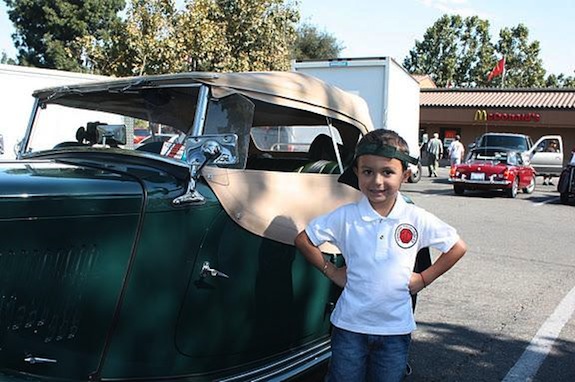
‘A spot of bother’
This young man, proudly displaying his ARR badged shirt is Cruz, grandson of members Brian and Jane Sonner. That’s his grandpa’s TC and his grandma’s MGB in the background. Hopefully to become a future Rough Rider!
Kimber Festive Call for Papers
Dick Knudson has asked me to include the following notice and as a member of the NEMGTR, I’m pleased to oblige.
The New England MG T Register is seeking proposals for papers to be presented at its Kimber Festival to be held in Norwich, New York, from April 20 through 22, 2012. The host site for the event is the elegant Northeast Classic Car Museum that has 150 magnificent classic cars on display.
The Kimber Festival is being revived after being off the calendar for several years. This meeting brings together enthusiasts who are keenly interested in M.G. history. Organized as an academic conference, the program consists of presentations about all M.G.s with topics that range from design and production to competitors and competitions. Papers about the last MGB will be as welcome as one about the first M.G., Old Number One.
Proposals for papers on subjects related to the old car hobby will also be welcomed. A few years ago, for instance, we had a presentation about flower arranging using M.G. parts. Following the Festival, a certain number of the papers will be selected for publication in The Sacred Octagon, the Register’s magazine.
Proposals should include the title of the submission, names and affiliations of presenters, together with addresses, phone numbers, email addresses of contact personnel, proposed format (paper, panel, workshop, etc.) and a one-page abstract describing the content of the presentation. A computer projector will be available. Proposals must be received by December 31, 2011; notification of acceptance is anticipated by January 31. Proposals should be submitted to: Richard L. Knudson, 9 St. James’ Place #207, Oneonta, New York 13820 USA, email preferred to FC7900 ‘at’ gmail.com.
Presenters pay all of their own expenses as there is no budget for honorariums. The registration fee will be $50.00 each and that includes a two day pass to the museum, a wine and cheese opening reception on Friday, and the Saturday evening closing dinner. The Friday evening wine and cheese will also feature a literature swap meet for books, sales literature, and photographs. The host motel room rate will be $65.00. Full details will be available on the Register’s web site: www.nemgtr.org
Following Part 2 of Eric Lembrick’s article on the SU Pressure Pump Type “L”, published in the August 2011 issue of TTT2, I have received a number of enquiries about fitting a transil. It seems that what has given rise to these enquiries is the following advice given in para 4.12 of the article:
“Finally refit the contact blade and a Transil to protect the points”.
Why fit a transil? The points on your SU fuel pump are at the mercy of the high voltage (up to several hundred volts) that is generated each time they open, causing them to arc. The basic explanation for such a high voltage (bearing in mind that your battery is only 12 volts!) is that it is an effect that happens each time a current through a coil is interrupted.
To negate this high voltage (i.e to limit voltage transients) the transil pictured below comes with a rated voltage. Below the rated voltage there is no connection between the two terminals, but above the rated voltage the terminals are connected together (dead short). Consequently, when the points break the high voltage which is generated across them is shorted out by the transil, so saving their burning and pitting.
Fitting the transil Fitting is simplicity itself. The transil is supplied with ready made solder tag connections. All that is required to fit it is a screwdriver.
Photo 1 – shows a transil with ready made solder tag connections along with transils awaiting fitment of the connections.
Note: Some T-Types will have been fitted in the past with a diode across the coil. Whilst this has proved to be an effective solution to reducing the voltage across the points it needs to be borne in mind that once a diode is fitted the pump becomes polarity sensitive. If a diode is fitted incorrectly, or, if fitted to a car of the wrong polarity, a pump fitted with a diode will fail instantly, causing the associated wiring to overheat or even catch fire. (The night after typing this I learnt from a TTT 2 ‘hard’ copy subscriber at our local ‘noggin and natter’ that he actually experienced this with his J2.
Photo 2 – shows a transil fitted to an SU pump.
The advantage of a transil is that it is completely non-sensitive to battery polarity. Hence a transil can be fitted either way around and a transil pump can be fitted to any car. It can also be left undisturbed if the polarity of the car’s battery is changed at a later date.
Transil kits, complete with fitting instructions are obtainable on a non-profit making basis from John James, 85 Bath Road, Keynsham BRISTOL BS31 1SR, UK. Cost, including postage is £3.50 (UK), and £4.00 outside of the UK. Payment by PayPal is acceptable.
If paying by PayPal please e-mail me at jj(at)octagon.fsbusiness.co.uk (substitute @ for at) and I will send you a PayPal invoice.
Your transil kit will be sent inside a normal correspondence envelope and when you open the envelope you will find the transil kit and fitting instructions inside.
Photo 1 showing rear lamp and stainless steel bracket fabricated by Adhoc Engineering along with the replacement inners for the 1130 sidelight on the front.
I love the simplicity of our old T-Type cars but over the last few years I have increasingly felt that sticking my arm out to let other traffic know that I am planning to turn or manoeuvre, was leaving me feeling a little vulnerable. It is fine when the hood is down and the sun shining. Visibility then is excellent but what about when the weather is inclement and the hood and/or side screens are up? When these are in place I find visibility is significantly reduced as well as accessibility to stick out the arm.
My car, like many other MG TDs in the UK, was re-imported from the USA and therefore had an indicator system fitted. However, as it was designed to meet 1950s American regulations it uses the existing white front wing side lights and the red rear brake lights. In short, the brake light doubles as the indicator. The wiring for me as a novice on these things seems complicated with the standard flasher unit wired through an additional relay that controls the indicator by interrupting the brake light if that is in operation.
When I purchased the car this was working correctly but after a year or two something in the system failed and I was unable to trace the problem, so for the last seven or eight years I have happily relied on hand signals. Not seeing any amber indicator lights on the car, the MOT station was content that none were fitted and passed the car every year.
Visiting the MG Restoration Show at Stoneleigh earlier this year I saw that Stafford Vehicle Components had produced a replacement light fitting for T-Types that fits inside the existing wing lamp housing. This fitment offered both white and amber bulbs and seemed like an excellent solution for the front. However there is nothing similar for the rear and looking around at other TD/TFs I found that everyone who had fitted rear indicators lamps had used all kinds of different lights, locations and fitting arrangements.
I decided that I wanted to fit something that was clear, looked period and could if wanted, be fairly easily removed should the car be entered for a Show (not that it ever is!). Also I didn’t want to drill any holes in the car.
The range of lights available on the market is extensive and in the end I went with a chrome torpedo light offered by SVC (+44 (0) 1827 67714) with the view of using the outmost bumper bar bolt as the fixing point. This would allow the lights to be aligned with the central crease in the rear wing and the brake lights.
A local engineering company “Adhoc Engineering” fabricated some stainless steel brackets that would allow easy fitting plus some adjustment to get the alignment just right.
As always, starting one task on an old car inevitably leads to another. On doing a trial run fit on the new rear indicator lights I noticed that the brake lights weren’t working very well and would probably fail the MOT that was due in a few days time. With the help of Brian Rainbow the fault was identified as the inline switch set in the in the hydraulic system. So that had to be replaced first. An easy task but as a precaution I also chose to replace the brake fluid and bleed the system which in turn highlighted a failure of the master cylinder which also required a rebuild or replacement. I digress!
Fitting the front replacement lights was easy following the instructions supplied by SVC. One comment in those instructions was to ensure the front mounting bolt didn’t foul the lower of the two bulbs, which was for the indicator. The first fitting clearly showed the bolt to be marginally too long so rather than pack it with washers I chose to cut off a couple of threads so they fitted perfectly. An additional earth wire was required for each wing lamp and that was easily fixed to the headlamp mounting bracket.
The rear lights were easily mounted thanks to the new brackets and wired through bullet connectors so they could be easily removed if needed. The aim was to use as far as possible the existing wiring loom and Brian had kindly looked at the TD wiring diagram and came up with a set of instructions I could follow.
Both the indicators and brake lights were wired through a relay located in the passenger foot well. As we had already installed a new brake light power supply wire to by-pass the relay as part of the previous investigation in to the faulty brake lights, this job was already done. The rest was fairly simple and a matter of removing the relay and reconnecting the wiring as per the instructions. Great, it should all work, except it didn’t……
I rechecked the instructions and all the wiring and as all seemed correct so it was time to call in the cavalry. Brian very quickly identified that the flasher relay was dead and I had wired the rear lights back to front assuming the black wire was earth and the coloured one live, which perhaps I should have checked out before fitting the lights.
With a new flasher unit and a quick swop over of the wires in the bullet connectors everything worked perfectly.
Colin Hooper
Photo 2 showing the location of the rear direction indicator lamp.
Photo 3 showing the aesthetically pleasing line of the rear direction indicator lamp in relation to the stop/tail lamp.
Wiring Instructions
Instructions to fit standard direction indicators to an MG TD with stop/flash relay installed.
Note: Wire numbers and colours are taken from the TD/TF workshop manual page N.23 “Wiring diagram for cars with separate control and fuse boxes, headlamp beam warning light, foot operated dip switch and provision for flashing traffic indicator lights”. The one exception is in Step 1 where the previous rewiring of my car has left a connection slightly different to that shown in the workshop manual.
Step 1 – Brake lamps
As these are wired through the Direction Indicator Relay as well and need to work independently of it, they should therefore be re-wired first. I suggest checking the operation of the brake lights before starting work to ensure there are no bulb failures.
1.1 Disconnect the green and purple wire (22) from the Stop Lamp Switch and tape over end of the unused cable.
1.2 Connect a length of new wire (ideally green with purple) from the vacant Brake Lamp Switch terminal to the rear of the car, connecting the end to a new double bullet connector.
1.3 Remove the white with brown wire (15) from the right-hand rear light from its current bullet connector and plug the bullet into the new double bullet connector used in the previous step.
1.4 Remove the white with purple wire (14) from the left-hand rear light from its current bullet connector and plug the bullet into the new double bullet connector used in step 1.2 above.
1.5 Test for the correct operation of the brake lights
Step 2 – Front indicators
2.1 Fit the replacement wing lamp bulb holders from SVC as per the instructions supplied with the units.
2.2 A new earth wire will be needed on each wing lamp as the new bulb holders are mounted in plastic fittings and do not earth though the lamp body to the wing as per the old units. I fitted a short length of black cable to the headlamp bracket bolt although it could probably be fed back to the new bolt retaining the wing lamp.
2.3 Test the side lamp operation (these work independently to the indicators).
Step 3 – Rear indicators
3.1 Fit the lamps as per supplier’s instructions or via your own home made bracket.
Step 4 – Wiring the new rear indicators (see Note)
(Note: in this paragraph the wire colour number is given first and Direction Indicator Relay Unit terminal number second)
4.1 Locate the Direction Indicator Relay Unit. (Mine was in the passenger foot well)
4.2 Label all 8 wires on the Relay (in case the wire colours do not match the workshop manual) with the numbers from the relay, then remove the wires from the relay unit.
4.3 Remove the Relay completely as it is no longer required.
4.4 Connect Relay wires green/red (18 numbered 2), white/purple wire (14 numbered 3) and green/blue wire (20 numbered 4) together using a double bullet connector. (I used a 15amp terminal connector block for this and the next actions and to isolate the unused wires rather than bullet connectors)
4.5 Connect Relay wires green/white (21 numbered 6), white/brown wire (15 numbered 7) and green/yellow wire (19 numbered 8) together using a double bullet connector.
4.6 Tape up Relay wire green/purple (22 numbered 5) as it is not now used.
4.7 Tape up Relay wire green/brown (23 numbered 1) as it is not now used.
4.8 Remove the other end of the green/brown wire (23) from Flasher Unit terminal L & tape it up.
4.9 Identify double bullet connector (17) with 3 green wires and remove the green wire that goes to the indicator switch common (middle) connection. Connect this green wire to the vacant Flasher Unit L terminal.
4.10 Connect left-hand rear indicator lamp to the old white/purple wire (14) bullet connector at n/s rear of car. Ensure that the wire from the indicator light is not earthed to the light body.
4.11 Connect right-hand indicator lamp to the old white/brown wire (15) at bullet connector at n/s rear of car. Ensure that the wire from the indicator light is not earthed to the light body.
4.12 Test that all indicators are working correctly.
(Option – fit a 12 volt buzzer in place of/or in addition to the Direction Indicator warning lamp as an audible reminder to cancel the indicators)
Ed’s Note: When I fitted direction indicators to my PB earlier this year I purchased the front sidelight conversion from SVC along with a pair of 1130 type lamps with orange lenses for the rear.
My recommendation would be to always fit a buzzer rather than a warning light. I’ve been in the passenger seat of a couple of cars with a warning light and I’ve had to tell the drivers to cancel their indicator switch on more than one occasion.
Torrington needle thrust bearing with hardened steel washers on the left which replaced the standard thrust washer on the right.
Recently I took my TA in for its annual MoT test, using a local garage that is sympathetic to classic and vintage cars. I was fairly confident it would pass OK, having greased all the suspension, adjusted the brakes and checked all the usual things prior to taking it to the garage. The mechanic, who knows my car well, gave it his usual thorough check over. He had the front axle up on a beam jack and checked all the front suspension for wear and seemed quite happy. He then asked me how much vertical clearance should there be on the kingpins; 4 to 6 thou came my swift reply. You better have a look at this then he said, and using a long lever under the front tyre he raised the wheel. To my amazement there was what looked like a tenth of an inch movement between the stub axle and the front axle eye. I won’t fail it on that, but make sure it’s not the same next year when you bring it here was his response!
The MoT test took place only a week before we were due to go away in the TA to attend the “T Register Autumn Weekend” up in the Yorkshire Dales. I anticipated covering about 600 miles that weekend, so I thought I ought to correct the thrust clearance before departing on that journey.
The next morning I was out in the garage early, and had the front end of the TA up on axle stands and set about stripping down the offside front suspension. To remove the kingpin thrust washer requires the kingpin to be drifted out of the stub axle. The easiest way to do this is to remove the front wheel, remove the front hub complete, then remove the 4 bolts that hold the brake back plate to the stub axle and steering arm. Once you have removed the 4 bolts, tie the brake back plate out of the way with a large tie-wrap, making sure there is no strain on the rubber flexible brake pipe. Once you have done this it is possible with a set of feeler gauges to measure the clearance gap between the thrust washer and the front axle eye. In my case it was not as much as I thought, it was 39 thou, but was still way outside the 4 to 6 thou that is acceptable, so I made a note of the clearance. Now I could undo the cotter pin that locates the kingpin and carefully drift it out. I removed the small nut that holds the kingpin top hat and felt washer in place and removed them. I could now drift the kingpin downwards until I could remove the stub axle and old thrust washer from the front axle. It was now time to wash the stub axle, kingpin and thrust washer with Jizer ready for re-assembly. The old thrust washer thickness was measured using a pair of callipers and was found to be 120 thou thick, so the thrust gap was 159 thou (120 + 39). I had a new spare kingpin set, so I was able to measure the thickness of a brand new thrust washer, it was 124 thou. It was obvious that I needed a much thicker thrust washer, but where do you get those from without making your own?
My solution was to use a Torrington bearing as the thrust washer. This is a small flat roller bearing that is 78 thou thick. You need to put an hardened washer either side of the Torrington bearing, and these are available in 3 sizes, being 32, 63 and 95 thousands of an inch thick. I used the Torrington bearing with two of the 32 thou washers, this measured 142 thou thick. I was still 17 thou under size, so I used a 10 thou shim from an MGB wheel bearing shim kit. This gave me a clearance of 6 thou once everything was greased and assembled back together. I put the 10 thou shim at the bottom between the lower Torrington shim and the stub axle. One thing to make sure of is when you replace the 4 bolts that hold the brake back plate, stub axle and steering arm together, clean the threads and use Loctite on assembly. Repack the grease in the front wheel bearings and reassemble using a new split pin in the castellated hub lock nut. Pump the kingpins full of grease before using the car. I had hoped that the Torrington bearings would make the steering a bit lighter, they may have done but I am damned if I can notice it. The TA has the highest steering ratio of all the T types, and is heavy!
The photograph shows the Torrington bearing plus two hardened washers along with the old bronze thrust washer, plus a selection of MGB wheel bearing shims. I have listed the part numbers of the Torrington bearings and washers below, along with the prices I paid for them at my local bearing supplier in September 2011 to give you a guide to the cost.
Torrington needle thrust bearing for ¾ inch shaft, NTA1220, £2-80 each inc vat Torrington thrust washer 32 thou thick, TRA1220, £1-94 each inc vat Torrington thrust washer 63 thou thick, TRB1220, £2-76 each inc vat Torrington thrust washer 95 thou thick, TRC1220, £2-82 each inc vat.
You can purchase a mixed pack of MGB front wheel bearing shims from Moss, part number ATB4242K (7 pieces) for £2-55. The shims come in 3, 5, 10 and 30 thou thickness.
Finally, if like me you also own an MGB in your stable, the MG Owners Club have for several years been supplying exchange MGB stub axles using Torrington thrust bearings in place of the old thrust washer/shims. They supply them ready pre-set and set-up, and you have the choice of needle roller thrust bearings or conventional shims.
Brian Rainbow
Back to school in order to calculate the combination of thrust washers and shims to use with the Torrington needle thrust bearing to take up the clearance gap.
Re-assembly complete with an acceptable clearance to satisfy the MoT tester… even with his crowbar!
The Lucas PLC switches fitted to early T-Types were quite robust, and all are of similar construction. The parts which get damaged are: the lock barrel, the switch knob and the bezel. To change the lock barrel (difficult to find now), the nut in the centre of the back of the case has to be removed. To replace the knob, or bezel the switch has to be disassembled. The PLC2 which came with TA0844 was intact with internals in good shape but the bezel will need to be re-chromed.
To start disassembly it is necessary to remove the nut soldered to the threaded spigot which is part of the lock barrel. This nut is located between the two centre terminals on the rear of the switch case. I used a gas soldering iron to heat until the solder melted and then sucked away the solder with a solder sucker. Sufficient solder can be removed this way to enable the nut to be unthreaded. Inserting the key will enable the lock barrel to be withdrawn.
At this stage the switch is being held together by its bezel. A twist of the bezel to line up with the release grooves in the casing should result in a handful of springs, washers and contacts. There are two springs inside and so controlled release of the bezel is necessary. Take a note of the order in which the switch comes apart as some time may elapse before the bezel is restored. (See photo 1).
Photo 1 – Take care in disassembling the switch!
The components were dirty with hard deposits of old Lucas grease, I cleaned all this with isopropyl alcohol, and had the bezel re-chromed.
The bezel will need painting and lettering. To do this, mask the edges and carefully take the shine off the centre lettered area using fine wet and dry paper. Spray with a thin coat of primer and a thin coat of satin black and leave to dry. With a fine brush, fill the grooves of the lettering with white emulsion paint and remove the surplus with damp lint free cotton material stretched over a finger. This will remove some paint from the lettering grooves. Leave to dry, fill these areas again as before until the lettering is complete.
Make two clips to fit into the groves on opposite sides of the switch case to hold the SRBP washer with the centre cut-out and contact ring. One, 5/8 inch wide for the groove adjacent to a grub screw socket and one ¾ inch wide for the other, I used welding wire. Now to the tricky part: how to fit together.
1/. First orientate the bezel so that its lugs fit the grooves in the case, because of the position of the lugs this can only be done in one position. Mark both with sliver of tape for locating later. Note that the lock barrel has a flat section at the thread end, this means that it only inserts correctly in one position. Note the position of the moulded projection in the centre of the switch case as viewed looking into the switch for later location of the lock barrel tube. Use tape to mark this.
2/. Place the knob into the bezel then put on the circlip cover dished side out, then the circlip, followed by the large plain SRBP washer then the large spring, with small end against the washer.
3/. Place the small insulation backed ignition contact ring into the case with contacts in location. Place its dished metal cover on top, dished side inwards. This metal cover has two cut away parts at its edge, the larger one should be against the projection moulded into the case close to its centre, Now ensure that the flat on the inside of the ignition contact ring lines up with the flat on its cover – it could be 90 degrees out. Follow this with the small spring, small end out. The small SRBF washer is balanced on top.
4/. Place a ballpoint pen through the centre of this assembly and slide the mazak lock body cover over the pen. The lock body cover has cut away parts on its inside end, with fingers either side. One side is deeper than the other which should line up with the small moulded projection near the centre of the case. The two fingers should fit into the slots in the back of the casing. It should not rock when pressed fully in, it is essential to get this orientation correct. Remove the pen. Look into the centre of the lock barrel holder and ensure that the flats on the inside of the ignition contact ring and its cover still line up. The cover can be moved with a small screwdriver.
5/. Dab some lubricant on the contacts in the case. (I used Servisol Switch Lubricant). Place the large contact ring into the case followed by the large SRBP washer with cut outs. Rotate both clockwise so that they stop at the projection on the inside of the case, check that the centre cut-outs line up.
6/. Fit the two wire clips in the grooves moulded into the sides of the switch case to retain the plain washer and large contact ring in position when pressed fully in. Secure the clips around the outside of the case with a broad elastic band (see Photo 2).
Photo 2 – Secure the clips around the outside of the case with a broad elastic band.
Note from photo 2 that the cut out in the centre of the SRBP ring at 9 o’clock is smaller than the other three and the projections at 2 and 5 o’clock are the same width but narrower than those opposite. This means that the knob will only fit in one position.
7/. Again ensure that the contact ring and its covering washer are rotated fully clockwise so that the cut away parts line up. With the large spring and the large SRBP washer on the inside of the switch knob, place the assembly into the switch case locating the narrow slots on the switch knob with the ones on the large contact ring and washer. There is only one position where the knob will fit.
The tape marks for the bezel location should be coincident and the knob should locate in the grooves when in the ‘Lamps Side’ position. Ease together until the bezel is firmly home and rotate it anticlockwise (viewed from the knob) until the bezel stop is reached. Remove the two clips. The knob will now be in the ‘Lamps Head’ position, check that the four knob positions can be achieved.
8/. Should things not work out at this stage, break for coffee and start again.
9/. Check that the flat on the ignition contacts ring are in line with that of its cover as in 6/. Insert the key in the lock barrel. Line up the flat near the end of the barrel with those of the ignition ring and its cover and insert the barrel into its housing. Slight wriggling might be necessary to achieve this. Screw on the nut (6BA) it can be soldered or locked with another nut.
With luck the lock can be rotated to complete the ignition circuit.
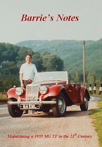
Barrie needs no introduction to many of you, especially those with TD or TF models. He is the TD/TF Technical Specialist for the ‘T’ Register of the MG Car Club and is also Registrar for the TF model.
I expect that Barrie has lost count of the hundreds of owners of these cars who have contacted him for advice concerning a problem with their T-Type; advice always freely given and unless he happens to be away, always given in a timely fashion.
Barrie has owned his TF1500 since February 1966 and his car has covered over 250,000 miles during his period of ownership. Who better then to write a book about maintaining a TF in the 21st Century!
Barrie’s Notes, a 76 page soft-back book covering every aspect of TF maintenance has sold nearly 500 copies worldwide. We have been fortunate in acquiring another twenty copies, which are on sale in the T-Shop for £6 plus postage of £0.92 (UK), £2.39 (EU) and £3.96 (Rest of World).
Barrie’s latest book on T-Types is titled The Essential Buyer’s Guide (to MG TD, TF & TF1500). Aimed primarily at prospective buyers of these models it is nonetheless useful if you already own one of these cars. It is available through the T-Shop.
They Started in MGs – Profiles of Sports Car Racers of the 1950s By Carl Goodwin, Forward by John Fitch. Published by McFarland & Company Inc. Paperback 7” x 10”. 283 pages. ISBN 9780786460526.
Whilst this book is exclusively about American racers and therefore of primary interest to US readers, it will no doubt appeal to those further afield. With many black and white illustrations, just over 80 drivers are profiled in alphabetical order with 3 or 4 pages on each. Of interest to us, of course, is that most of them started in TCs, but there are many who began in TDs and even a few in TFs before they progressed on to other makes.
Whilst many of the drivers will be unknown to readers outside the USA, some reached international fame and will be familiar to all, but their starts in motor racing will probably contain some unknown facts for most people. Here are some of the more well known names included:
S H Arnolt – the brains and money behind the Arnolt TDs. Briggs Cunningham – who eventually had his own cars at Le Mans for many years. Richie Ginther – one of the few Americans in Formula 1. Phil Hill – arguably the most successful American in Formula 1 Karl Ludvigsen – motoring photographer and author. Steve McQueen – enough said! Ken Miles – the Englishman who went to the US, famous for his MG specials. Al Moss – founder of the Moss parts companies. Carroll Shelby – Cobras, Le Mans etc! The author, Carl Goodwin, was himself a racer and has many articles to his credit in a host of motoring publications which have won him many awards. John Fitch, who wrote the foreword, is himself profiled and tells us his very first sports car was a lemon coloured TC in 1948!
A must have for MG book collectors like me but for others, worth adding to your Christmas lists for an interesting read in the holidays.
POLYURETHANE BUSHES FOR TCs & TD/TFs
I have continued to nag the supplier about a completion date. At the end of October I received a response from him as follows:
MGTC Bushes, only received the metals today so will be about 6 – 8 weeks before we’ll have 200 off each – so it seems we might just have them before Xmas.
I followed this up with a strongly worded e-mail, which said that customers would be extremely disappointed with this news and could I at least have some indication of the price so that I would have something to pass on to customers (who have been extremely supportive with orders from all around the world).
All went quiet and I was just about to pick up the phone on Thursday 10th November when the supplier rang me and gave me some prices as follows:
Part no. 0073 (shorter bush) £1.60 plus VAT Part no. 0074 (longer bush) £1.63 plus VAT Cost of moulds £200 plus VAT ( for the two)
I have ordered 200 of each bush and amortised the cost of the two moulds over the 400. Therefore, I make the non-profit selling price (to get my money back!) to be £2.79 each. This is around one third of the price of those available from a commercial supplier and mine are correct and do not need trimming.
Well over half the bushes have been pre-ordered and I will be contacting customers as soon as I have them. I’ll be asking for an (optional) small separate donation to the TTT 2 ‘hard’ copy fund with each order sent.
RADIATOR MASCOTS (from Jeremy Evans)
“I read with pleasure and interest the latest edition of the TTT2 – as usual, a great read to chase away the darkening evenings.
The article on the ‘Midge’ radiator mascot was particularly good, but I have one observation for you. In 1937 the Road Traffic Act was modified to preclude the use of radiator mascots and calorimeters and such like in the interests of safety. Fitting a mascot like the ‘Midge’ to a car made after 1937 therefore runs contrary to the Road Traffic Act and cars fitted with these should fail their MOT and in the event of an accident the owner could, if the mascot caused any injury, be liable in any personal injury claim.
Having had vintage cars, with lovely mascots and calorimeters, I wanted to fit a ‘Midge’ to my TC, but this legislation prevents me, I wonder if a word of warning would be appropriate to warn other UK T-Type owners that the fitment of anything to the radiator other than the original octagonal cap might land them in hot water”.
This website uses cookies to improve your experience. We'll assume you're ok with this, but you can opt-out if you wish. Cookie settingsACCEPT
Privacy & Cookies Policy
Privacy Overview
This website uses cookies to improve your experience while you navigate through the website. Out of these cookies, the cookies that are categorized as necessary are stored on your browser as they are essential for the working of basic functionalities of the website. We also use third-party cookies that help us analyze and understand how you use this website. These cookies will be stored in your browser only with your consent. You also have the option to opt-out of these cookies. But opting out of some of these cookies may have an effect on your browsing experience.
Necessary cookies are absolutely essential for the website to function properly. This category only includes cookies that ensures basic functionalities and security features of the website. These cookies do not store any personal information.
Any cookies that may not be particularly necessary for the website to function and is used specifically to collect user personal data via analytics, ads, other embedded contents are termed as non-necessary cookies. It is mandatory to procure user consent prior to running these cookies on your website.