


Polybushes

The following was received from Barrie Jones:
“When visually checking my TF recently I noticed some blue particles under the rear end. The polyurethane bushes fitted to the rear spring shackles were flaking at the edges. These are usually regarded as “fit-and-forget” so it came as a surprise to me. I raised the rear end and dismantled one of the shackles. This is what I found (above photo). All 8 bushes had turned crystalline and were no longer doing their job properly.
I keep detailed maintenance records so I looked up when I fitted them. It was 17 years ago!
So, they do last longer than rubber bushes, but they are not everlasting”.
The following from Michael Sherrell who received it from John Canty:
XPAG CROSSFLOW ALLOY HEAD
“The other day some interesting information arrived from TC owner John Canty in the UK.
He has an 8 port, alloy, crossflow, XPAG head made by Robert Cowell (later Roberta Cowell), the origins of which are unknown to me, but in 1954 Mike Costin acquired one whilst working with Colin Chapman on the Lotus 8, Frank Costin’s first streamliner SAR 5. The original heads had a small ‘Cowell’ cast in the side, but the Chapman ones did not!
John came across the head at a motor spares place when he went looking for a pair of SU air rams. We could be so lucky! His head does not have the ‘Cowell’ cast in, so it might be a Chapman one. John was a TC racer (TC/1403) back in the days when TCs filled the grids in the UK. He could have done with the head then!
The story gets more intriguing: with the letters and photos John sent me, came a photocopy of a letter addressed to him from Keith Duckworth himself (of Cosworth Engineering) dated 10/05/91. In it he outlined some of the history of these heads and it goes like this: It was Mike Costin who was with Colin Chapman at the time – 1954 – He had just returned from holiday. They used a crossflow aluminium head, which was made by Robert Cowell – who incidentally became Roberta Cowell by the assistance of the odd operation or two. Some heads had a small COWELL cast on the side of the head. The Lotus had not got the Cowell name (and we all know why!). Had a leak from pushrod hole to exhaust port, which Mike Costin lined with a copper tube. Mike and I think the heads were very rare… Best Wishes, Keith Duckworth.
Looking at the photos, one can see the spark plugs have been shifted to the off side to be with the four individual inlets and enter the (minimal) combustion chambers over the inlet valves. There appears to be little of no water flow block to head and minimal oil drain head to block. One can only guess at the compression ratio (high) and it would be pretty difficult to blow a head gasket with all that flat area. Exhaust ports are round, as are the inlets. The whole design looks vert appealing, pity they are so rare.
I believe these heads may be the source of some confusion over the Laystall Lucas alloy heads, sometimes thought of as crossflow heads, which they were not. I would like to thank John Canty for going to trouble and expense to share this interesting bit of XPAG history with us.
Almost as interesting as the heads themselves is the story of Robert Cowell, who later became Roberta Cowell after a series of operations, becoming a forerunner of gender change. It’s worth looking up Roberta Cowell on line. Spitfire pilot, racing driver, talented engineer and pioneering transgender person, just a bit ahead of her time”.


TC gearbox end covers


The following from Paul Busby:
“Thought you would like to see my latest efforts to suitably improve one of the weaknesses in TC’s design. Other people have remanufactured the gearbox end cover or offer steel splint plates but I have re-visited the issue. Clearly failure occurs through the engine/gearbox combination moving forward through normal traction and braking loads, accident, soft and perished mounting rubbers, flexure in the engine mount plate and chassis mount brackets which do not offer much resistance to longitudinal movement.
Hence the need for additional ribbing around the cantilever section of the end cover. In addition to increasing the stiffening rib arrangement around the common failure line, I have enlarged the output shaft spigot to accept a modern lip seal. The seal runs on the original, reverse scroll section of the drive flange which is covered by a SKF ‘super sleeve/shaft repair sleeve’. A 36mm repair sleeve is a perfect fit. – see photo. If needed, the end cover can be left bored as original to run the reverse scroll.
Second photograph includes one of an original end cover (un-broken, pretty rare). Due to making the outer rib parallel, the arrangement needs the M10 studs to be longer and for ease of availability the M8 csk bolt is replaced by a M8x30 Allen cap screw.
I have so far only made end covers for my own use but if there is enough interest shown (Minimum of10), I would make a batch. Alloy is LM25 heat treated to TF condition.” pyb.7(at)tiscali.co.uk [please substitute @ for (at)].
Also available from Paul are these gearbox remote top covers, as these break and wear at the gear lever ball causing the lever to drop through the actuator arm.

Thin steel gaskets for tappet chest cover
All 20 of these have now been sold, along with the 40 nitrile cork gaskets.
I have recently ordered some spare nitrile bonded cork gaskets. Whist they are not to hand at the time of typing this, they should be available by the time that this appears.
I have yet to fit my steel and nitrile bonded cork gasket set (been too busy refitting the back axle on my TF) but when the time comes, Paul Ireland has sent me the following ‘instructions’ on how to do it:
“To fix, I would recommend using a good quality gasket sealant such as red Hermetite or Loctite SI 5980 Gasket Sealant Paste. Put a thin coat on one side of one of the cork gaskets then press it onto the steel plate.
Put a thin coat of gasket sealant onto the exposed side of that cork gasket and offer the steel plate up to the cover, using two of the fastening bolts to locate it.
You can then put a thin coat of sealant on one face of the final cork gasket face and put it onto the steel plate. Coat the final face and offer the cover and steel plate up to the engine, using the fastening bolts to keep everything aligned.
It’s probably easier than fitting the original cork gasket.
However, please be aware it’s not a magic fix to the oil leaks, it just helps to reduce them.”

Loctite SI 5980 (other brands are available).

KMG 568 (TA3145)

This is Martyn Lister’s TA, rebuilt by Martyn over a 10-year period from 1988 to 1998. Daniel, Martyn’s son, is trying to trace the history of the car prior to 1986. Contact him at daniel.lister86(at)gmail.com [Please substitute @ for (at)].
Unknown TC
I have Cathelijne Spoelstra of The MG Workshop in The Netherlands https://www.mgworkshop.nl/en to thank for this wonderful period photograph.

Cat sent me the link to the photograph and I followed this up with Leeds City Council. The copyright is owned by Brian McGrath (that’s Brian in the centre of the photo) and I have since had the pleasure of speaking to him. The TC (chassis number and registration number unknown) was owned by Mr Duckworth, the woodwork teacher at Burmantoft’s boys’ school. He also owned the Wolseley 15/50 parked behind the TC.
Brian told me that the Woodwork Centre was housed in an annex to Burmantoft’s girls’ school and the boys had to walk 200 yards from their school to attend woodwork lessons. This mixing of the sexes was frowned on by Duckworth inasmuch as if one of the boys was spied watching the girls playing netball, a suitably sized off-cut of 2” x 2” timber would be launched at the miscreant. Another penalty for misbehaviour was to wash one of Duckworth’s cars.
PTD 634 (TD26502)


Chris Wing is enquiring about the TD he used to race. When Chris bought this ex-Lancashire Constabulary Police Car in 1967 it came with some racing history, but he wanted to make the car more competitive. The TD’s brakes and suspension were improved and the engine rebuilt to Stage 2 with larger SUs and a Derrington 4 branch manifold. The work was carried out by Alex, a Polish employee of Archway Engineering in Manchester.
Chris recalls burning out the clutch during a race meeting at Brands Hatch and driving home (to the Peak District of Derbyshire – at least 200 miles) without a clutch! A new clutch was subsequently fitted by Alex, who came to Chris’ house to do the job.
By 1970, with another family addition on the way, Chris needed to get his priorities in order, so the car was sold. It was purchased by Archway Engineering, who, of course, knew the car.
All the time I was typing this, I kept thinking that there was something familiar about the chassis number. It then dawned on me that it must have been something to do with my DVLA work for the MG Octagon Car Club (I do so many registrations that I can’t exactly recall each one to memory). I looked up my database and hey presto I found that I applied to reclaim registration number PTD 634 on behalf of Jim and Sheila Paterson in August 2020.
Jim and Sheila have owned the car since 1971, but it was taken off the road in November 1974 and has been ‘sleeping’ in the garage until last year when Jim decided to get the TD restored on his retirement. It has been at the premises of Yorkshire Restorations in Shipley, North Yorkshire (formerly Naylor Bros) for some months waiting for Jim to go and give it ‘sign off’, but unable to do so because of Covid 19 restrictions.

A restored TD26502 at the premises of Yorkshire Restorations in Shipley.
So, there you have it – a ‘Lost’ and an immediately ‘Found’ item! Chris has been in touch with Sheila and Jim.
KLM 237 (TA????)

Mike Dalby of the Triple-M Register has been in touch on behalf of a chap, whose father owned a 12/12 M-type and then a TA. His name was Cyril Stanley West and he bought it new when he was in the RAF. It would be a great shame if such a fine-looking car has not survived, but it doesn’t come up on the DVLA search facility. Mike can be contacted at mikedatum(at)sky.com [please substitute @ for (at)].
TC10189 (formerly NPH 750)
As we learnt in the previous issue with KKD 600 (TC9581), it sometimes takes a few years for a ‘Found’ reply to catch up with a ‘Lost’ enquiry.
This has been the case with TCI0189 about which the late Simon Parker was asking in Issue 37 (August 2016). Simon was trying to find information about his late uncle’s car, which has trials history from competing in Cornwall, and also race and rally history, including participating in the 1951 RAC Rally.

We said at the time that the car was no longer traceable through the DVLA and now we know why. In March, just after the April TTT 2 was published, I received an email from Steve Tofield from across ‘the pond’ with the following message:
I am happy to report a found TC! I was assiduously pursuing my study of all things TC last night and read in Issue 37 of August 2016 that Simon Parker in the UK was trying to find information about his late uncle’s car, TC 10189. The car, reg # NPH 750 was no longer traceable through the DVLA.
I bought the car a few weeks ago in Maine and until now knew nothing of its history other than build date. I am beginning a frame off restoration of the car and am very happy to be able to participate in its resurfacing! I have emailed Simon at the email address provided in Issue 37 but have since heard that he died last October. Would be very happy to receive (and give) any info regarding history of TC 10189.
TC2259 (XSU 390)

Colin (Tweed) Harris is trying to trace the whereabouts of TC2259, his first TC. The last Tweed saw of it was at Brown & Gammons, where it was traded in for TC0632. Colin has a fair bit of history which the present owner might be interested in.
TC2259 was reimported from California in the late 1960s. It had a few non-standard features, such as Morris Minor rack & pinion steering and a Volvo 144 gearbox. Colin can be contacted at lizandtweed(at)yahoo.co.uk [Please substitute @ for (at)].
TC0632 belonged to the late John Huddleston. It was nicknamed ‘Mickey Mouse’ by John and had been in the same family since 1962. It sold for £24,000 at British Car Auctions (BCA) Bridgwater (Somerset) Auctions some years ago; it attracted a great deal of interest and the successful bidder was a dealer.
I knew TC0632, since John and his brother-in-law, Jack Emdall from Canada, came to see me with the car – from memory they called to collect some kingpins. John lived at Portishead, west of Bristol, so he would have had a 15 mile drive to my house, which is east of Bristol.
John’s wife Karen, pre-deceased him (they were on holiday at the time) and John subsequently died suddenly. He died intestate, which meant that the value of all his possessions went to the British Government.
TC1353 (was KNE 764)

Oliver Richardson has contacted me to say that he has a handful of photos from when TC1353 was being rebuilt in late 70s/80s. If the owner is known he is happy to pass them on.
The car is thought to be in the US; if the owner cares to contact me, I will arrange with Oliver to get the photos to him or her. Please contact me at: jj(at)ttypes.org [Please substitute @ for (at)].
DKT 634 (TA????)
This car was featured in the April issue on behalf of the former owner, Kevin Morrison. Kevin was surprised to read that I’d moved him from Cyprus to Malta. I now have to write out 100 times “Kevin Morrison lives in Cyprus”.
Kevin, who definitely lives in Cyprus, has recently sent me a pic of his TC, ‘Matilda’, following a 2-year restoration.

The pic shows Kevin returning from an MOT. Clearly delighted, Kevin sent me the following:
“My MG TC, ‘Matilda’, passed her MOT with flying colours today, even though the MOT man was totally confused how things worked on the car. So, I had to show him! ….. and it was so enjoyable to drive a real car for a change.
The MOT only costs €35 for 2 years, and we get 60% discount on Road Tax (will cost about €70 a year) if the car is registered with FIVA.
And that’s for everyday use. Or I can have the option of only paying €25 a year just for weekend use only”.
JK 9843

Chris Blood posted this pic on the Triple-M forum. The chassis number is unknown and it doesn’t show up from the DVLA search facility. This TC was registered to Caffyns (Eastbourne) Ltd on 18/9/47.

This article was last published in Issue 42 (June 2017). It has since been updated for Paul’s book ‘Classic Engines, Modern Fuel’ and what you are about to read is Chapter 4 of Paul’s book. I have been granted permission to reproduce Chapter 4 by Rod Grainger of Veloce Publishing Limited to whom I am most grateful.
Search on the internet for information on how petrol engines work and you will find the answer: “there are four cycles, induction, compression, ignition and exhaust”. Or as described in this chapter, suck, squeeze,bang and blow. However, the operation of these engines is more complex than this simple description. To help the reader appreciate the results of the Manchester tests, this chapter introduces some of the concepts affecting the combustion of fuel in a four-stroke spark-ignition engine. It describes the journey taken by a single cylinder in an engine running at 3000rpm. While the valve timings apply to an XPAG, they are virtually identical to any petrol engine, old or new.
Our piston completes the four stages of the cycle in 40 thousandth of a second (40ms). Think how fast one second is and imagine that 1ms was the same as one second. On that timescale, one minute would last 17 hours! It would take around 11 hours for our cycle to complete. 1ms is so fast that even gasses act like solids.
Suck

The start of our journey is when the piston is at Top Dead Centre (TDC). At this point you might expect the exhaust valve to snap shut followed by the inlet valve opening as quickly. Valves cannot open and close instantaneously. Delays in opening the inlet valve reduces an engine’s power. The engineers who designed these engines knew valves could start to open earlier or close later than expected.
At the start of our journey, the inlet valve will already have begun to open. It started to open 0.6ms (11o before TDC). The exhaust valve is still open. It will take another 1.3ms (24o after TDC) before it closes.The 1.9ms when both valves are open is called valve overlap. This is beneficial at higher rpm.
At the top of the ‘blow’ stroke, the piston has expelled most of the exhaust gasses. As the inlet valve starts to open, a “scavenge” effect takes place. The rush of gasses into the exhaust port draws in air/petrol mixture through the inlet valve.
At TDC the cylinder is not empty. The 45.5cc combustion chamber (about 15 per cent of the 312.5cc cylinder volume) still contains 1200oC exhaust gasses from the previous cycle. As the piston starts the ‘suck’ stroke, these will continue to vent through the exhaust valve until it closes 24 o after TDC. The remaining hot gasses will cool as they expand. If you ever studied Physics, you may remember Boyle’s Law: as a gas expands, it cools, and when compressed it gets hotter.
As the piston falls it will reach the point where the pressure in the cylinder becomes lower than the inlet manifold pressure. The air/fuel mixture will start to flow into the cylinder. Induction has begun.
The volume of mixture entering the cylinder is controlled by the throttle butterfly. This is a brass disc that pivots when the throttle is pressed. As it rotates, it reduces the area of the restriction in the inlet manifold allowing more mixture to flow into the engine. As more air flows through the carburettor, the suction piston responds. It moves upwards withdrawing the tapered needle from the jet. This allows more fuel into the air stream. The way the SU or variable jet carburettor works is described in more detail in Chapter 5.
To get the greatest power from an engine, the suck cycle needs to induct as much air/fuel mixture as possible. In a normally-aspirated engine, the volume of mixture entering the cylinder depends on engine capacity. As petrol vapour occupies about 14 times the volume of liquid petrol, the more liquid petrol that can be inducted, the greater the power output.
Superchargers or turbochargers increase the pressure in the inlet manifold, forcing more mixture into the cylinder. This is why these engines generate more power than normally-aspirated engines with the same capacity.
Depending on throttle setting and engine rpm, around 10% of the petrol will evaporate in the carburettor, cooling it. The remaining 90% will enter the engine as different sized droplets of liquid petrol.
In normal road use, when the engine is running at part throttle, the volume of petrol evaporating in the carburettor will not be noticeable. However, for those who want to maximise power output, it reduces the overall volume of petrol entering the engine and hence its power. Additionally, the cooling effect can also cause the carburettors to ice up, especially on cold, damp days. This is more likely in engines with exposed carburettors such as motorbikes.

As discussed in Chapter 2, modern petrol has more front endcomponents than classic petrol. These evaporate at lower temperatures. This has two negative effects on carburetted engines. Firstly, it increases the volume of petrol evaporating in the carburettor. Less liquid petrol is inducted, reducing power output. Secondly, it increases the cooling of the carburettors, increasing the risk of icing.
The first air/fuel mixture entering the cylinder meets the residual hot exhaust gasses. These heat the incoming mixture evaporating some of the petrol droplets and cooling the residual gasses in the process. Even though these are extremely hot, they will not contain enough energy to evaporate all the inducted petrol.
The inlet valve on many two-valve per cylinder engines is offset to the side of the cylinder. The advantage of this is that it causes the inducted mixture to swirl during the suckstroke. This both helps the petrol droplets disperse in the air and increases turbulence, something that is very important during the ‘bang’ cycle.
Before petrol can burn, it must be a vapour. To get the optimal mixture for the bang cycle, all the liquid entering the cylinder must evaporate or boil and mix with the air. This boiling is unlike that in a kitchen kettle used for water. In a kettle, bubbles form in the bulk of the liquid. Because the suck cycle is so fast, the petrol in the cylinder can only evaporate molecule by molecule from the surface of the droplets. The small droplets with a large surface area relative to their volume, evaporate the fastest.

Squeeze
After reaching bottom dead centre (BDC), the piston starts to rise. Induction continues for another 3.2ms (57O after BCD) until the inlet valve closes. During this time the air/fuel mixture entering the cylinder some 90mm above the piston, does not feel the effect of its upward motion. The mixture continues to flow into the cylinder. This increases the cylinder pressure about 0.2 to 0.5lb/in2 (140 to 350kg/m2) above that of the inlet manifold. This is called the stagnation pressure.
The ‘squeeze stroke does not start in earnest until the inlet valve has closed. It continues for another 6.8ms until the piston reaches TDC, after 20ms or halfway into our journey.
During this stroke, the pressure and temperature of the mixture increases. This provides extra heat to evaporate more liquid petrol.

Pockets of rich and weak mixture will form as the liquid petrol evaporates. Turbulence in the gases disperses these pockets as the squeeze stroke progresses.
In common with many modern designs, the combustion chamber in the cylinder head of the XPAG is boat shaped. As a result, the outside edges of the cylinder head overlap the bore.
As the piston approaches the top of the stroke, the gasses on the outside edge are ‘squished’ into the combustion chamber, increasing turbulence and mixing.
At the end of the compression stroke, liquid petrol may still be present in the cylinder. This can be trapped between the piston and cylinder wall, around the valves, or as large droplets of fuel that have not evaporated. Even if the carburettor is delivering the correct mixture, the presence of liquid petrol results in a weak mixture at the end of the stroke.

Bang
There are two ways the vapour of a flammable liquid can ignite. The flash point is the lowest temperature at which an ignition source, such as the spark plug, can ignite the mixture. The lowest temperature at which it will spontaneously ignite, burning without a source of ignition, is called the autoignition temperature.
Autoignition is very bad for an engine. It causes the pressure in the cylinder to rapidly increase, resulting in pinking or knocking. This is a mechanical tinkling sound that occurs typically at full throttle and low rpm. It sounds like pebbles being shaken about in an empty tin. An ideal fuel has a low flash point and high autoignition temperature. The higher the octane rating of the fuel, the higher the autoignition temperature.
The XPAG, in common with many older engines, has a low compression ratio of 7.25:1 compared with 9:1 or higher in modern engines.
In the 1950s, improved petrol quality allowed compression ratios to be increased. With higher compression ratios there is more heating of the air/fuel mixture during the squeeze stroke, and more liquid petrol will evaporate. Its final volume is smaller, allowing it to burn more efficiently. These engines produce more power than lower compression engines of the same capacity. The main disadvantage is that the engine is more prone to pinking or knocking caused by the mixture autoigniting during the compression stroke.
Compression is initiated by an electrical spark in the gap of the sparking plug.
After the sparkplug fires, combustion takes place in three phases:
As petrol burns, the hydrocarbon chains break down; the hydrogen (H) combines with the oxygen (O2) in the air to produce water (H2O). The carbon (C) combines with the O2 to produce carbon dioxide (CO2). Each litre of petrol liberates a huge 33 million joules of heat energy – enough to boil 100 kettles of water. The heat energy from the burning fuel increases the temperature of the gasses to over 2000oC.
The theory Boyle’s Law states that as the temperature of a fixed volume of gas increases so does its pressure. As the pressure increases, it forces the piston down the cylinder. This is how the engine converts the heat energy in the petrol into power.
As the piston falls so does the temperature and pressure of the gasses. Greatest power is produced when the pressure in the cylinder reaches its peak at 17 o or 0.9ms after TDC.
After the spark plug has fired, it takes approximately 2.6ms for the mixture to burn and reach peak pressure. To provide enough time for this to happen, the sparkplug needs to be fired before the piston reaches the top of its stroke. This is called ignition advance. Simplistically, the time to reach peak pressure is constant and independent of rpm. Hence, as rpm increases, and the piston is moving faster, the sparkplug needs to be fired earlier in the cycle to give the same time for the fuel to burn. A graph showing the ignition advance against rpm is called the advance curve.
Typically, at 3000rpm, the sparkplug is fired 30o before the piston has reached TDC. A race begins. As the flame front grows and the pressure in the cylinder rises, it is working against the piston which is still moving upwards. At 30o advanced, the piston still has 8.5 mm to travel (9.3% of the stroke) before it reaches TDC. Knocking or pinking causes rapid increases in cylinder pressure before the piston reaches TDC. This puts an excessive load on the piston and big end bearing causing damage.
On 1930s and earlier cars ignition advance was set manually, typically by a lever on the steering wheel. On later cars this is done automatically by bob weights in the distributor. These fly out as engine rpm increases.
The growth of the initial fireball also depends on the pressure of the air/fuel mixture in the cylinder. This is mainly dependent on throttle setting, not, as may be expected, compression ratio. At light throttle settings, cylinder pressure is low and the growth of the flame front slower. To give more time for the air/fuel to burn, it is necessary to further advance the ignition timing. On later cars this is done by a vacuum pod on the distributor. This is connected to the inlet manifold to measure its pressure. This, in turn, is a measure of throttle setting. Earlier cars do not have a vacuum advance.
Maintaining the correct ignition advance is important. Running an engine too advanced will result in pinking or knocking and damage to the piston and big ends. Running too retarded increases the exhaust temperature, resulting in burned pistons and exhaust valves and damage to the cylinder head.
The ‘bang’ stroke suffers from a problem called ‘cyclic variability’. The time taken for the air/petrol mixture to burn critically depends on a number of factors.
These include the air-to-fuel ratio (AFR) around the sparkplug, the level of turbulence in the gasses, etc. Even with a precisely timed spark, minor differences in these factors cause the timing of the peak pressure to vary on each cycle. This is discussed in Chapter 6.
Unfortunately, the power stroke ends all too quickly, 7.1ms after TDC when the exhaust valve starts to open (52o before BDC). The high pressure gasses rush out of the cylinder in a process called ‘blowdown’. Blowdown utilises the remaining combustion pressure to “get the gas in the exhaust moving”. Without this effect, energy would be lost during the exhaust stroke as the piston would have to push the gasses out of the cylinder.
Each piston is powering the car forward for just 18% of the time of each cycle.

Blow
If the combustion were perfect, a mixture of water vapour, carbon dioxide and nitrogen rushes into the exhaust, expanding and cooling to around 500oC. The piston reaches BDC, 2.9ms after the exhaust valve started to open. As it rises, the remaining exhaust gasses are pushed out of the cylinder.
Unfortunately, combustion is not perfect; petrol vapour requires oxygen to burn. Droplets of petrol that vaporise late in the cycle leave pockets of poorly mixed vapour. Although the temperature is sufficiently high to cause these to burn, the absence of oxygen means they will not burn properly. They result in unburned hydrocarbons or carbon monoxide in the exhaust gasses. As the unburned hydrocarbons travel down the exhaust system they may mix with oxygen. As they burn, they further increase exhaust temperatures.
A gas analyser reveals a great deal about the combustion process. The unburned hydrocarbons show how much petrol has been unable to burn in the cylinder or exhaust due to a lack of oxygen. This can arise either because of a rich mixture or poor combustion as described above. NOX or nitrous oxide, (NO) is produced at high combustion temperatures when the nitrogen in the air oxidises. NOX is bad for three reasons : it uses energy, reducing the engine’s efficiency; it reduces the amount of oxygen available for the fuel to burn; and it’s an atmospheric pollutant. The presence of NOX is usually an indication of high ignition temperatures caused by a weak mixture.
In contrast, high levels of unburned hydrocarbons or carbon monoxide indicate insufficient oxygen. This is either due to a rich mixture or poor combustion.
What about modern cars? While the valve and ignition timing will differ slightly from an XPAG, the journey described above is very similar. There are three main differences:
At 3000rpm, our journey ends after 40ms only to start over again. Each cylinder completes the cycle described above 25 times per second. As you can see from this brief description, it is far more complicated than just induction, compression, combustion and exhaust.
Ed’s note:
The link to buy Paul’s book Classic Engines, Modern Fuel is: https://classicenginesmodernfuel.org.uk/Clubs/ModernFuel/Book.aspx?dyn_menu_mainmenu=1000001
Paul is donating all the royalties from the book to helping children with their schooling in Tanzania. Issue 65 (April 2021) of TTT 2 contained an article about this.
I’m absolutely delighted to say that the book has been an outstanding success, with copies sold all around the world.
The book’s 152 pages are divided up into the following chapters:
Paul has owned his TC since 1967. He bought it for £60 from his mathematics teacher in school. His father was pretty dismissive about the car that Paul was going to buy, saying that it was a load of rubbish! However, Paul was supported by his mother and the sale went ahead.

The car as bought, back in 1967.

The car as it is now – pic taken in 2020. It has been rebuilt twice.

If you have read any of Neil Cairns’ authoritative books on M.G. Engines, you will know that the MPJG engine used in the TA was based on the old Morris 10/4 Series 2 side valve engine, but with an overhead valve conversion. This engine was initially fitted to the 1935 Morris 10/4 Series 3 (MPJM), and the Wolseley 10/40 (MPJW) cars before being used in the TA. It had a bore of 63.5mm and a stroke of 102mm, giving it a capacity of 1292cc.The stroke of 102mm goes right back to the early Morris Bullnose engines.
The MPJG engine with its long stroke, un-counterbalanced crankshaft, heavy flywheel and wet clutch, plus a cylinder head with siamesed inlet and exhaust ports, was never going to be a high revving engine. However, it did have good pulling power and loads of torque.
Now that these engines are approaching 86 years old, I frequently get requests asking if I know where there is a good TA crank for sale. Sadly, they are few and far between these days; there are still quite a few old rusty cranks about, many with cracks and ground to the maximum, so be careful buying an old one!
Such a request, 6 years ago by Mike Williams, led me to look at getting a small batch of new TA cranks made. Mike, who ran a restoration business, had good contacts with the MD of Gosnays, a long-established engineering company in Essex. At that time, I had a spare standard crank plus an old 1938 Laystall counter-balanced crank that was made for the TA Trials cars. This crank had been ground to – 60 thou and had a crack on number 4 journal. I sent both of these cranks to Adrian Wilkes of Gosnays to get a batch of 5 new counterbalanced TA cranks made. Adrian would not disclose who made them, but they did a superb job. However, they were not cheap at £1850 plus VAT each. Mike had one, as did Roger Muir and myself; I sold another one for Gosnays, but I can’t remember who to, and later Tim Parrott purchased the last one.
If you look at the photo below, which shows four crankshafts, they are from left to right: a Morris 10/4 Series 2 crank, a standard MPJG crank, the old Laystall crank used in the TA Trials cars, and the new Gosnay crank.
I have to confess that I have not used mine yet – it sits in the bottom of a wardrobe awaiting the next engine rebuild, along with a new Newman camshaft and a set of followers.
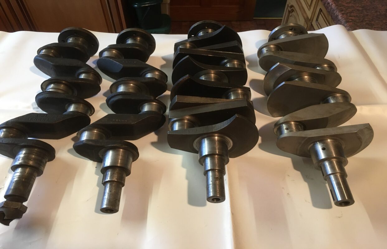
Photo 1
I purchased the old Morris 10 crank with a view to seeing if it could be fitted to a TA engine, the only difference is in the nose (see photo 2). This would necessitate a new crank pulley to be made to move the pulley out by 42mm to line up with the water pump and dynamo pulleys on the TA (see photo 3). Not such a big problem and second-hand Morris 10 cranks are more readily available and have probably not had such a hard life as a TA crank.

Photo 2

Photo 3
I have recently found a small engineering firm about five miles from my home, who make crankshafts, their speciality is a longer throw crank for Sunbeam Lotus engines to increase capacity. If they can make crankshafts for high-revving Lotus engines, then making TA cranks should be a piece of cake! When we come out of lock-down, I will call on them and get a quote to make another small batch of say, 6 TA counter-balanced cranks, similar to the Gosnay one (see photo 4). If you are genuinely interested, drop John an email and I will keep you informed of progress. Incidentally, one TA owner I spoke with this week was quoted £1365 plus VAT to have his old crank metal sprayed and ground back to standard size. At that price, a new crank does not sound excessively expensive. Brian Rainbow.
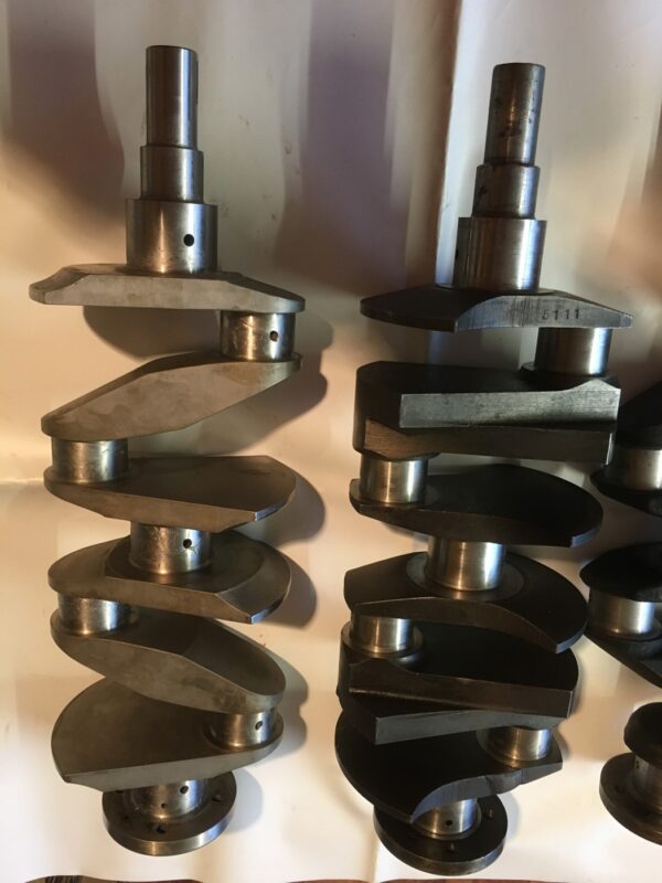
Photo 4

by Charles Penny
I bought my first MG (TIZI) at 17 years old but the learning process started a year earlier. At 14 I was sent away to school. If they had known the trouble they were admitting, they would have refused entry.
In 1957 the Queen was due to open the newly built workshops as part of the school’s 400-year anniversary celebrations. They were empty, painted pristine white throughout, and full of all the new lathes, tools, ramps, benches and woodwork equipment that I could dream of. I was allowed early access to build a 16ft sea going canoe as an example of the student’s woodworking skill. I promptly took the opportunity early on Sunday mornings to make a set of keys to several of the school doors, including the double doors of the workshop.
At some point, before I discovered girls, I had seen my first MG, fallen in love with the concept, and decided that I needed a sports car. Having no money, I robbed my childhood piggy bank and purchased an old ‘sit up and beg’, running, black Ford Pop for £5 – the going rate at the time. At that tender age I thought that all you had to do to make a sports car was to cut the top off a saloon! The seller agreed to deliver it into the workshop double doors early one Sunday morning.
Charlie, my best mate, and I, realized that a hacksaw would take ages and thus, having seen someone cutting metal with an oxy torch on the television, decided it was the quickest way to turn the Pop into an MG (of sorts). All went well ‘till, never having worked on a car before, and not realizing that the petrol cap was connected to the tank by a two- inch pipe, we cut straight through it. There was the most-almighty bang! The whole workshop went instantly black; black soot absolutely everywhere. Immediate expulsion from school a certainty. The shame and disappointment of the parents unbearable. Never mind the cost and telling the Queen to come back later! We literally could not see six inches in front of ourselves. We stood still, stunned.
No-one had appeared, it was still too early. After a while the air began to clear. The soot began to settle and joy of joys, the pristine white walls were still pristine white. Every horizontal surface was covered in thick soot which we spent the next two hours frantically sweeping up. The wreck of the Pop was pushed out of sight and later disposed of. We made a hasty retreat.
The moral of the story is:
Six months later I bought ‘Tizi’, my first true love and who is still with me 55 years later. But that is another saga.

Pictured above, the Ford Popular, known affectionately as the Ford Pop, was introduced in 1953 and followed on from the Ford Anglia. Charles’ car would not have been in the condition of this (almost certainly restored) example.

CRB 539 is ‘TIZI’, a 1936 TA, pictured here with 16 years old Charles in the driving seat in the grounds of his school.
I’m not sure how ‘Tizi’ came to acquire that rather substantial looking front bumper bar, but it was on the car when Charles bought it.
‘Tizi’ has recently been given a beautiful transformation at Adrian Moore’s bodyshop (‘Finishing Touch’) in Weston-super-Mare and Charles is currently waiting for a V5C from DVLA, which will show his reclaimed registration mark, CRB 539. It’s all go!

Complete new stub axles have up to now been available, but the supplier has stated that there will be no more produced. An option is to replace the spindles, which are now well over 70 years’ old. Eric Worpe explains how it is done.
Several TC friends have decided to replace their stub axle spindles after hearing about occasional spindle failures. I became concerned after seeing that the newly installed spindles had turned blue from overheating, despite being fitted by a respected engineering company.
The replacement spindles are intended to be an interference fit in the bored out old stub axle forgings. These have to be expanded by heating to allow the new spindles to be dropped in.
The degree of heating should be well below the original tempering temperature of the carbon-alloy steel forging. The original heat treatment would have been chosen to give both strength and fatigue resistance, qualities that could be degraded by overheating.
The new spindles on the other hand, are either left at room temperature, or preferably pre-cooled in a freezer compartment. In the case of the blued replacement spindles, the stub axle forgings must have been heated to a point where they were able to transfer enough heat to raise the temperature of the spindles to 300 deg. C.
My concerns persuaded me to have a go at fitting new spindles; these were obtained from Bob Grunau in Canada and a friend kindly volunteered his broken stub axle for the experiment.
The stub axle was secured in a machined disk held in the chuck of a lathe. Photo 1 shows the boring out operation on the stub axle. This is nerve-racking, as the bore has to be machined quite accurately to give an interference fit of between 1.5 and 2.5 thou. of an inch. Photo 2 shows the bore being measured.

Photo 1 – the boring out operation.

Photo 2 – measuring the bore.
The main purpose for the interference fit is to clamp the spindle so that it is unable to rotate when the spindle’s nut, securing the ball bearings and the spacers to the stub axle, is tightened. The new threads (3/4” UNF) are more substantial than the original threads, and will need new TD/TF stub axle nuts, which should be tightened to 125 ft.lb. to ensure rigidity of the whole assembly.
When the nut is correctly tightened, the inner races of the ball bearings and the spacers form the effective diameter of the spindle as far as bending forces are concerned. This reduces the dynamic fatigue stresses experienced by the actual spindle, a very good reason for not leaving out the spacer when taper bearings are fitted.
The new spindle is secured by its button head, which is pulled up against a machined shoulder in the stub axle when the spindle’s nut is tightened.
Heating up the stub axle and forcing the replacement spindle into position is a one chance only operation. If the spindle is slightly misaligned whilst being driven into the stub axle, then it could seize up as the stub axle shrinks due to cooling down and thus fail to seat correctly.
To help alignment, a jig was fabricated (Photo 3 below), from a heavy brass tube in which a nylon piston was free to float, but supported by a compression spring in contact with a sturdy base, which screws in to the bottom of the tube.


Photo 4 – shows the nylon piston floating at the top of the tube with the stub axle about to be located on the rim of the tube.
The nylon piston has been bored out to hold the new spindle so that when the spindle is inserted through the stub axle into the piston, its shoulder floats just free of any contact with the stub axle (Photo 5). This should set up and maintain the alignment of the spindle as it is forced into the stub axle to the point where the button head makes contact with the shoulder in the stub axle.

Photo 5
It’s important that the spindles’ nuts are correctly tightened, as the integrity of the stub axle now depends on this aspect. The extent of the interference-fit and how to achieve it has been worked out as follows:
If we choose to heat up the stub axle in a domestic oven, or in a hearth to 220 deg. C, we can aim for a temperature difference between the stub axle and spindle of some 200 deg. C, (allowing for a frozen spindle and some cooling down of the stub axle during the transfer to the alignment jig).
If the coefficient of expansion of steel = 12 x 10(-6)/deg. C, then on a diameter of 1.125”, 200 deg. C would produce an expansion of:
1.125 x 200 x 12 x 10(-6) = 2.7 x 10(-3) or 2.7 thou. of an inch.
So, an interference fit of 2 thou. +/- 0.5 thou. is a practical starting point.
Machining the stub axle bore to such limits calls for considerable care. The cutting tip sits on the end of a long boring bar and consequently lacks rigidity; any dulling of the cutting tip results in a deflection error. Fortunately, I obtained a David Brown adjustable floating reamer (Photo 6), which enabled an accurate final cut of the bore.

Photo 6 – the David Brown adjustable floating reamer.
After the insertion of the new spindle, a small part of the button head is often needed to be ground away to allow clearance for any “flashing” on the axle eye’s forging.
Some compensation in the location of the spindle in the stub axle is needed if taper roller bearings are to be fitted, due to their inherent offset.
I’d like to thank Clive Manser for taking photos 1 to 5 and giving me encouragement and Roger Warren for the many chats on machining that have enabled a small part of his engineering expertise to be passed on to me. He describes me as “a bit of a Fred Dibnah”, which he might think is a term of disparagement, but is, in fact, high praise to me.
Ed’s note: Eric tells me that he is prepared to do a limited number of these stub axle replacements. He can be contacted at: e.worpe(at)btinternet.com [Please substitute @ for (at)]
Eric also has a few TC kingpin bushes for sale – these are bi-metal bushes, known as ‘wrapped bushes’ and are exactly the same as fitted when the cars were new. Contact details as above.
For a set of 4 the cost is 32 GBP. For orders of between 3 sets of 4 and 9 sets of 4 the cost is 30 GBP per set of 4. For orders of 10 sets and above the bushes can be purchased for 28 GBP per set of 4.
Postage at cost on all orders.
These prices are not very much above cost and only made possible by arranging a bulk order.

Bi-metal ‘wrapped’ kingpin bushes – note the oil/grease groove which has a spur take-off that feeds lubrication to the thrust faces of the beam axle’s ‘eye’.

Bi-metal ‘wrapped’ king pin bush showing the spur groove that feeds the thrust washer.
Ed’s further note: Quite a few readers will be wondering who on earth is Fred Dibnah! This from Wikipedia….
Frederick Travis Dibnah, MBE (29 April 1938 – 6 November 2004) was an English steeplejack and television personality, with a keen interest in mechanical engineering, who described himself as a “backstreet mechanic”. When Dibnah was born, Britain relied heavily upon coal to fuel its industry. As a child, he was fascinated by the steam engines which powered the many textile mills in Bolton, but he paid particular attention to chimneys and the men who worked on them. He began his working life as a joiner, before becoming a steeplejack. From age 22, he served for two years in the Army Catering Corps of the British Army, undertaking his National Service. Once demobilised, he returned to steeplejacking but met with limited success until he was asked to repair Bolton’s parish church. The resulting publicity provided a welcome boost to his business, ensuring he was almost never out of work. In 1978, while making repairs to Bolton Town Hall, Dibnah was filmed by a regional BBC news crew. The BBC then commissioned a documentary, which followed the rough-hewn steeplejack as he worked on chimneys, interacted with his family and talked about his favourite hobby—steam. His Lanky manner and gentle, self-taught philosophical outlook proved popular with viewers and he featured in a number of television programmes. Toward the end of his life, the decline of Britain’s industry was mirrored by a decline in his steeplejacking business and Dibnah increasingly came to rely on public appearances and after-dinner speaking to support his income. In 1998, he presented a programme on Britain’s industrial history and went on to present a number of series, largely concerned with the Industrial Revolution and its mechanical and architectural legacy. He died from bladder cancer in November 2004, aged 66. He is survived by his five children from his first two marriages.

Fred Dibnah – picture courtesy of wiganworld.co.uk
So, now you know!
I have sent a small donation to Wikipedia as I have used them before and it is not fair to expect to use their research for free when they rely on donations to keep afloat.
I have also sent a small donation to Grace’s Guide. This registered charity is the leading source of historical information on industry and manufacturing in Britain. This web publication contains 146270 pages of information and 231762 images on early companies, their products and the people who designed and built them.
I used Grace’s Guide for my research in compiling the Armstrong Shock Absorbers article.

The company was formed in 1926 by Fullerton George Gordon Armstrong as The Armstrong Patents Company with a factory in Beverley, North Yorkshire.

F. G. Gordon Armstrong (born 1885) had an engineering background, serving as an apprentice from 1902 to 1906 at Clarke, Chapman and Company, who were old established marine and electrical engineers and boilermakers, based in Gateshead, Tyne and Wear. Following his apprenticeship, he served as a Marine engineer on the SS Kura until 1907, when he became Chief Mechanic at North Eastern Garages in York. Not one to let grass grow under his feet, he went on to found the East Riding Engineering Works in Beverley, where he designed and produced the Gordon Cyclecar from 1912 to 1914. This was powered by a 9 horse-power V-twin JAP engine.

He is also credited with building an aeroplane, which was said to resemble a Bleriot, but with a triangular chassis and larger tail.
Armstrong’s Patents Company, which started producing shock absorbers at its factory in Eastgate, Beverley in 1926, became a private company in 1930. In 1935 it was formed as a Public company, known as Armstrong Shock Absorbers Ltd with The Patents Company continuing as the operating company.
By 1939 the company was producing 4,000 shock absorbers a day and employing 450 workers; it was clearly a major manufacturing concern.
Now aged 60, F. G. Gordon Armstrong handed control of the company to his son, William, who established a research and development facility in Fulford on the outskirts of York.
In 1949 William Armstrong opened a new factory in York to manufacture a new type of suspension unit for Ford cars and to establish the company’s range of telescopic shock absorbers.
If you Google ‘Film Armstrong patents East Gate Beverley shock absorber taken in 1954’, you can view a fascinating film of what life was like on the Armstrong production line at its Beverley factory in 1954. Doubtless, if you own a late TD or TF, your shock absorbers would have been produced at this factory.
The film was taken by local film-maker, W. E. Jackets, a retired police inspector and is of 17 minutes duration. There is a slight pause about half way through (the screen goes black), but it starts up again.
Of particular note in the film is that the majority of workers in the factory were women (no equal pay in those days!). There was very little space between the workers and the various machines, and whilst one might think that the whole operation seemed rather chaotic, it was obvious that each individual knew exactly what s/he was doing. My favourite part of the film was watching men pouring molten metal into the moulds and after a while, ‘cracking’ the moulds open to reveal the shock absorber bodies.
In 1961, Armstrong Shock Absorbers changed its name to Armstrong Equipment, with the subsidiary, Armstrong Patent Company Ltd.
The 1960s was probably the most successful period for the company, as it now had three manufacturing divisions; the one making shock absorbers, one making Helicoil screw inserts for repair of spark plug threads and one making “Strongarm” door closers and hydraulic remote controls. Total number of employees in the group was now around 4,000.
The York factory was expanded in 1965, but just six years later, employees were warned that up to 250 of its work-force could be laid off, due to disputes in the Ford motor company and postal strikes.

Armstrong Patents Company factory in 1980 (photo courtesy of ‘The Press’ which featured a series of nostalgia galleries on old York workplaces).
After years of UK-wide industrial strife, and as foreign-built cars grew in popularity, the company announced another 400 redundancies in York in 1980. A year later, the Beverley factory, where it all started, closed with the loss of 300 jobs.
In1986, Armstrong’s was diversifying by making replacement exhausts for cars; the company won an appeal to the Law Lords against British Leyland to be allowed to make such exhausts without payment of royalty to BL.
Fears the York factory would close in 1986 were averted, but then in 1989, after losing a £3.3m contract with Nissan, the company was sold to the American firm Tenneco and the York factory became Monroe’s. Further redundancies followed, and the factory closed in 2000 with the loss of the remaining 392 jobs. At one time the company had factories in Australia, Canada, the United States and South Africa.
Mention has been made of Helicoil screw inserts; these have got me out of trouble (recovering stripped threads) on a couple of occasions. Here is a period advert.

There is also a short film (less than 5 minutes) taken in the Heli-Coil division of the Beverley factory. It is not as interesting as the one taken in the shock absorber division. Google ‘ARMSTRONG PATENTS EAST GATE BEVERLEY HELI-COIL DIVISION’.
So, what is the legacy of the company started all those years’ ago by Fullerton George Gordon Armstrong?
We have previously noted that the shock absorber division was sold to the American firm Tenneco, which took over Monroe. The latter company became a Tenneco brand in 1977.
New Armstrong rear shock absorbers are still available for late TD, TF and MGA from NTG Motor Services and from the MG Octagon Car Club. I am not sure who makes them, but I could not find any reference in the Monroe catalogue.
I am also not sure what happened to the Armstrong Helicoil division (unless it was sold to Tenneco, along with the shock absorber division). I have noted that an old-established company by the name of Böllhoff, manufacture threaded inserts, but as far as I could see, there was never any ‘tie-up’ with Armstrong. Böllhoff manufactures a vast range of fasteners, including locknuts with special HELICOIL® NUTS for secured screw joints.
As for the division making “Strongarm” door closers and hydraulic remote controls, with Armstrong’s concentrating increasingly on the automotive market, the remote control equipment manufacture was transferred to James Lyon & Sons, a Merseyside company, in 1970. This company adopted the Armstrong name through its association with Armstrong Patents and is now known as Armstrong Lyons Hydraulics.
Fast forward 65 years+ and Armstrong shock absorbers are still in use on our cars. I’ve just had my rears reconditioned by Raj Patel in Leicester and I’m very pleased with them. Here’s a picture, taken on return from Raj.


Welcome to Issue 66, June 2021.
The front cover shows Steve Poteet’s recently finished 1946 TC restoration. Steve owns M.H. Frank Ltd., a small men’s clothing store in Clemson, South Carolina. In 2014, a customer, knowing of Steve’s love of MGs, offered to sell him his father’s TC. Thinking this would be a great addition to his collection – a 1962 MGA and a 1953 MGTD – Steve headed to Atlanta with a trailer.
The late Hank Rippert, President of the New England ‘T’ Register recommended Paul Johnson of Pinehurst, North Carolina for the restoration. Of course, there were issues. A new old stock tub was found in Lexington, Kentucky. Barry Walker in England helped with the lamps and horn. Craig Seabrook in Ohio recalibrated the instruments and the burled walnut dashboard. Sammy Jordan worked his magic on all the metalwork, including the paint job. Steve even contacted the first owner of the car in Scotland to determine the original colour scheme.
Six years later, the 1946 MGTC came home to Clemson. Steve’s only complaint is there is not enough time to drive it!
The age profile of T-Series owners means that there will be an increasing number of us who pass away as the years go by. Gerry Brown, a leading figure in UK M.G. circles for more than 40 years died on 10th March. Ian Linton, who contributed a number of articles to this magazine, died at the beginning of April. In Australia, Vale Ken Stewart-Richardson died on 9th February. Ken, who was in constant pain for months said to Michael Sherrell with a smile on his face from his hospital bed, a week before his death, that he wanted his last ride to be in a TC. Taken aback, Mike had no idea as to how this could be done, but he assured Ken and his wife, Mary Ann that he would somehow find a way to fulfil his request. Turning to ‘wizard engineer’ John Bowles for help, JB did a few measurements and calculations, consulted with the funeral bods, and came up with a light, simple, three-piece frame to go into Mike’s TC and to be screwed to the wooden floor. It had to work first time and it did, as the pictures show.


Derry Dickson’s TC ‘Matilda’ is currently up for sale and has attracted a lot of interest. It was featured in Issue 63. Another TC (TC3335) is for sale, located in the SF Bay Area of California. Both cars are on the ttypes.org website.
Later in this issue you will find a period advert for ‘The MG Super Sports Morris’ dated November 1923. This has been provided, courtesy of Brian Rainbow of the MG Octagon Car Club, who received it from one of his members. The first recorded sale of this model was in August 1923 and this advert from The Isis (a student publication at the University of Oxford, where the magazine was established in 1892) is further confirmation (if further confirmation was needed) that the centenary of M.G. should be celebrated in 2023 and not 2024. Despite this, I’ve seen what is probably the latest strapline from MG, which reads ‘FINDING SOLUTIONS SINCE 1924’. Where do they get their information from?

Peter Hehir, Public Officer of the M.G. T Type Owners & Restorers Club, based in Australia, has been in touch to say that since the Club’s formation (which was reported in Issue 60 of TTT 2, June 2020) membership, which spans five countries, has grown to 175. It has been decided to cap the membership at 200 and applications received above this ceiling would go on a waiting list. An outline of the Club’s aims, activities and objectives was given in Issue 60 of TTT 2. For further information, please contact Peter at peter.m.hehir(at)gmail.com [please substitute @ for (at)]. Since joining the TTORC I have to say that I am hugely impressed with the Club’s bimonthly magazine.
This issue contains an article by Eric Worpe on TC stub axle spindle replacement. Eric has recently obtained a small stock of spindles and is prepared to fit them for owners. Eric’s contact details are at the end of the article.
How quickly the year has gone by! Those of you who receive a printed copy of the magazine will find a subscription renewal note with this issue. Despite increases in postal charges, subs remain the same.
