TD owner, Gerry Wood, has been trying for the last eighteen months to get to the bottom of his XPAG overheating problem. He just about made it there and back (from Bath and return) to the TTT 2 weekend in Mid-Wales, but it involved several stops, particularly after climbing hills.
All the usual diagnostics were tried (compression test, timing, blocked radiator, etc.,), but to no avail. Then one day…… Gerry takes up the story……..
“Having removed the water pump for the 2nd time, and nearly putting it back because I couldn’t see anything wrong, I looked down the pump inlet pipe and right at the elbow where it bends to the impeller, I found debris which almost completely blocked the water flow to the pump. I think the debris probably came from the bottom of the radiator.
Attached is a photo of the offending blockage (the coin is a 5p piece). After a 20 mile test run in hot sunshine, up two steep climbs, the water temperature never exceeded 86 degrees C.”
Replacement headlamp bulb for TC
I had an enquiry (one of several I get every week!) about where to source an EL602 bulb. I referred the enquirer to NTG Motor Services and he reported back that he managed to purchase a suitable equivalent from NTG.
TD two bow and three bow hoods
Another enquiry concerned the changeover date for two bow and three bow hoods for the TD.
The answer is TD20374 for LHD cars and TD20696 for RHD cars when the original frame was replaced by the 3-bow design with the third bow fitted to give slightly more cockpit headroom. The sidescreen frames were altered to suit.
Clocks4Classics
Lionel Uden reports excellent service from this company as follows:
Ed’s note: Lionel is one of many satisfied customers of this company. Peter Cole wrote a useful article in Issue 45 about the services offered by the company.
‘Raiding Party’ from Sweden
I’ve been going through some of the many e-mails I’ve received from Gabriel Öhman over the years. Gabriel and his friend, Björn Erik Lindh used to regularly come over to England to buy spares. This photo, taken in 1975 shows “a pile of J2s”, as Gabriel described the haul, purchased from a chap in Sussex.
The 3.8 S-type Jag (remember those?) belonged to Gabriel and was a useful tow-car. Having loaded up, they went on their way, but were stopped by police as they did not have the same registration number on the trailer as the one on the car (which apparently is illegal in Sweden as the numbers must not be the same). When the traffic policeman realised that our two spares hunters were from Sweden he said “Why can’t you use a Volvo as other Swedes do and I wouldn’t have stopped you – I thought you were English!”
This follow up to the short article in issue 54 reveals the progress made. The oil pump issue stems from the concern about the diminutive circlip provided in some oil pump rebuild kits. Alarming numbers of damaged engines due to the failure of the circlip are coming to light, so identifying those pumps that have been rebuilt and rectifying any potential problems becomes a cause célèbre.
My first consideration was, can the oil pump be removed from my TC with the engine in situ? Yes, it can, but quite a bit of dismantling is called for. The pump needs to clear both the chassis rail and front wing skirt to allow some 4 ½” of the pump body to be withdrawn. Lifting the front of the engine to the limit where the bell housing collides with the ramp plate, just about allows the pump to clear obstructions. However, this means removing the bonnet, the radiator, oil pipe to the filter, front wing fixings but excluding the stanchion fixtures and front engine mounting bolts. I also removed the exhaust down-pipe and some of the bolts securing the rear gearbox flange to the rubber mounts, but now suspect this may not be necessary.
The front of the engine should be jacked up, using a chunky bit of wood to spread the load on the sump. Partially undo the pump’s securing bolts but ensure they can be eventually returned to their original position or better still change the bolts to HT socket cap types. If any threads need cleaning up, use a very blunt 6 mm plug tap (1 mm pitch) to reform rather than re-cut the threads.
Leaving the end cover loosely in place, try to withdraw the pump’s body. It’s likely some encouragement is needed to split it away from the engine block, in which case use a soft aluminium drift to jog the body away from the block. Once free, undo the bolts and remove the pump’s end cover making sure the idler gear doesn’t drop out. The relationship between the gears ought to be kept the same. The pump’s body can now be slid out, clearing the chassis and the wing, which can be swivelled outwards around the stanchion’s pivot.
If the oil pump’s driving gear is secured to the shaft by the replacement circlip shown in photo 1, then, having gone to all this trouble to remove the pump, a replacement is probably advisable.
Photo 1 – the EN16 squeeze clip was made by the author (Eric Worpe) and is referred to later in this article.
Two choices can be considered:-
Doug Pelton recommends and stocks a HD Spiral Retaining Ring (CCL 094) (see Spirolox), which consists of two coils of a thin flat spring shown in sketch 1. These should be more robust as they have a 360 degree engagement in the shaft’s shallow groove. However, they are not easy to install.
Sketch 1 – the Spirolox retaining ring stocked by Doug Pelton of ‘From the Frame Up’.
The grooves on replacement 13 mm dia. drive shafts are rather shallow, as advised by the circlip specifications, eg. Dia. of groove =12.4 mm, internal dia. of circlip =11.9 mm, suggesting a groove depth of only 0.3 mm to allow some spring pressure of the circlip to be applied to the groove diameter when installed. This shallow depth of engagement is unfortunately a consequence of the need to prevent the possible overstretching of the circlip when being expanded over the 13 mm dia. shaft. I must admit to being uneasy over such a shallow groove, so my feelings are that the groove should be deepened for an alternative fixing.
Deepening the groove may be complicated if the end of the shaft has also been “case hardened”. If this is the case (sad pun!) then the hardened skin needs to be ground away with a diamond abrasive disk driven by a Dremmel type electric motor. The motor is mounted on the tool post of a lathe and the shaft is held in a rotating chuck, (photo 2).
Photo 2 – deepening the groove.
The groove depth on an original shaft was about 1 mm, so that seems a good value to aim for. All of this does assume the availability of a lathe which can then be used to make a suitable “squeeze to fit clip” from a non-springy material.
For the EN16 squeeze clip shown in photo 1, an EN16 alloy steel bar was initially chosen as it is both high tensile and easy to machine, an important consideration when coming to “part off” the machined clip, (photo 3). A ¾” dia. (19 mm) bar of EN16 was drilled to fit the shaft dia. of 13 mm and then “parted off” to give the required thickness.
Photo 3 – making the EN16 squeeze clip.
The thickness of the clip was matched to the open groove width after the shaft and gear are assembled in the pump. Sometimes the groove width is partially covered by the gear so feeler gauges are used to measure the available groove width, which should be at least 1 mm.
A 60 degree segment was cut out of the ring which should allow the clip to be closed around the 11 mm dia. groove with pliers, (refer back to photo 1)
As this idea is a leap into the unknown, it seemed prudent to test the 3 types of clips i.e. (1) the original replacement circlip. (2) Doug Pelton’s Retaining Ring, and (3) the home made “squeeze in” type. A 13 mm dia. bar with 3 grooves of 11.6, 11.6, & 11 mm dia. simulating the pump’s drive shaft was machined up and a mild steel block with a 13 mm bore with a slight chamfer was used to simulate the spur gear. Pressure to force the shaft into the block, stressing the circlip under test, was provided by a hydraulic press.
Photo 4 shows the test set up with the original replacement circlip about to be tested. The hydraulic press provided a force of over 4 tons and photo 5 shows how the clip deformed into the chamfer but still remained in the somewhat distorted groove.
Photo 4 shows the replacement circlip about to receive some metallic torture and photo 5 shows that it didn’t submit!
The next test on the Pelton Retaining Ring (photo 6), also went to over 4 tons force and again deformed the ring into the chamfer and distorted the groove leaving a short portion of the ring displaced out of the groove.
The final test on the EN16 “squeeze in” clip located in the deeper 11 mm dia. groove (photo 7), ended with a “bang” at just over 4 tons force. The clip had neatly sheared with part of the ring still located in the groove.
Photo 6 shows that the Pelton Retaining Ring withstood the force, but the EN16 “squeeze in” clip shown in photo 7, didn’t.
The final Photo 8 shows all 3 tested clips and the dummy shaft, the only clip that failed was mine.
All 3 clips were able to sustain forces far greater than would be found in practice, the chamfered bore of the spur gear does not seem to compromise the security of the clip as I had originally thought. It might even allow a wedge effect to develop, although this could vary from batch to batch depending on the machining of the chamfer. So why do the replacement circlips fail? My own circlip had been in the pump for 10,000 miles and seemed fine. I’m left wondering if some circlips have been overstretched when being inserted.Care is needed to only expand the circlip enough to just slide over the shaft, anymore risks deforming the circlip, resulting in a loose fit within the groove.
My choice of EN16 steel needs reconsidering as its shear strength seems low. An 18 mm HT bolt may provide a suitable material to try out. How do these tests compare with the original clip? I was able to try one out and took the press up to 6 tons force. Again, the clip deformed to the chamfer profile but was otherwise unmolested, so I’ll reuse it in the pump once it’s flattened.
Photo 8 – shows the three tested clips and the dummy shaft.
Eric Worpe
Ed’s note: A big ‘thank you’ to Eric for his analysis of the problem and the tests he carried out. Based on the tests, it would appear that some replacement clips sold as part of the oil pump rebuild kits could be OK if carefully fitted, although we do not yet know how they fail. Doug Pelton’s HD Spiral Retaining Ring (CCL 094) seems sound, based on a static stress test, but then so does the original replacement circlip if both are properly fitted.
However, without the security of a retaining system based on a deeper groove, those shafts with a shallow groove system leave something to be desired. Knowing Eric, he will continue to experiment.
Chris Keevill, who is the Early MG Society’s (EMGS) Newsletter editor, enquired a few TTT 2 issues ago, as to the whereabouts of his family’s old T-Types (all of which come up when using the DVLA search enquiry facility).
Information was sought about a cream TD, registration mark AFL 972, chassis number TD9712, which used to belong to Chris’ brother, who is now in Perth, Western Australia. Here’s a period photo of his brother taking part in one of the many driving test competitions that he used to enter.
AFL 972 was traced to current owner, David Barnes (with a little bit of help from Dynamo and Starter Motor electrical engineer, Chris Wallis). David kindly sent a couple of photographs of AFL 972 which were scanned and sent to Chris. Here’s one of them:
David took the trouble to write, giving some history of the car. He bought it from a work colleague in February 1984 and having been off the road for several years, it needed a full body-off rebuild.
When the car was finished, DVLA were not helpful about re-instating the registration mark AFL 972, even though the green log book was produced; an age-related number was allocated instead. Undeterred, David enlisted the help of his Member of Parliament, Edwina Currie, and AFL 972 was once again on the car’s number plates.
One snippet of information about which David may have been unaware when he bought the car is that the TD was fitted with a factory replacement gearbox. When Chris’ bother bought the car from a North London dealer it had a dodgy first gear. The salesman made light of this saying words to the effect that “you don’t need first gear on these”. This was a mixture of good and bad news, the good being that it presented an opportunity to negotiate the price downwards and a deal was done.
As luck would have it, the local village garage happened to have a factory replacement gearbox in stock, which had been ordered in for a customer. The customer had failed to turn up to have the gearbox fitted, so it was surplus to requirements. This being the case the garage generously donated the gearbox!
Chris also sought information about a 1954 TF, which was owned from almost new by his mother. TTT 2 cannot claim credit for tracing MRK 713 (TF 5368) – credit should go to Enjoying MG, the monthly magazine of the MG Owners’ Club. The Owners’ Club ran a feature on the cars formerly owned by Chris’ family in the letters page of the June issue of Enjoying MG. Current owner and Owners’ Club member, Michael Smailes, noticed the feature and got in touch with Chris via the Club. Mike bought the car from Richardson’s of Staines as a 21st birthday present to himself in 1968. Here’s a picture of the TF with Mike’s son in the driving seat and Mike in the passenger seat.
I’ve since been in touch with Mike and I’ve sent him a copy of the Production Record for TF 5368. Originally finished in black cellulose, it was one of 36 TFs built on 6th May 1954. I’ll also be sending him a copy of this TTT 2 issue and a complimentary reproduction sales brochure for the TF.
We still need to help Chris trace his brother’s TC (KNA 494) pictured below:
Just to recap, its chassis number is TC8208, shown from a DVLA enquiry as a maroon TC ‘Not taxed for road use.’
Chris has received some more information about TC8208 from his brother as follows:
“The TC was part exchanged for my Matchless Twin on 5th Jan 1957. 90 pounds for the Matchless against 389 pounds for the MG. Balance to be paid off over 24 months at an interest rate of 12.5% PA. All from Charles Simpson of Staples Corner on the North Circular.”
Chris has managed to find a Charles Simpson advert in Motor Sport of December 1956; this is reproduced below (the prices will make you weep!). His brother’s TC was one of several TCs offered in the advert. Chris thinks that his brother still has the original invoice!
Chris can be contacted at earlymgs(‘at’)icloud.com [please substitute @ for (at)].
Postscript: Chris also enquired about a P-type, registration mark AVK 187, which his brother purchased after TD9712. Unfortunately, he never finished restoring it. A major problem contributed to the unfinished restoration; this was that the car was left outside (as one did in those days) and one cold night it sustained a cracked cylinder block. Unlike today, when virtually every replacement part can be obtained for a Triple-M car, spares were exceedingly difficult to come by back then (the only realistic option being a tour of the local scrapyards).
The car comes up when using the DVLA search enquiry facility as ‘Untaxed, tax due 01 October 2013’. It is chassis number PA0715. I have contacted the Triple-M Register of the MGCC as the car is known to them. Let’s hope they can help!
TA???? (EXP 528)
John Cooper has requested assistance in finding out if his old TA still exists. He can’t remember the chassis number, but says he sold it back in 1971. The car doesn’t come up from a DVLA search enquiry and is not known to any of the MG clubs.
The picture shows him doing some grass track testing in about 1962/3. It had an XPAG engine and 16″ wheels and balloon tyres, all the rage then. j-jcooper(at)ntlworld.com [Please substitute @ for (at)]
TA0635 (CBJ 84)
Dawn Smith is trying to trace this TA, owned by her husband in the late 1960s. It comes up in response to a DVLA enquiry and is shown as being on a SORN notification. Any leads to the editor, please at jj(at)ttypes.org [Please substitute @ for (at)]
TA???? (EKD 635)
Not much to say about this 1938 TA. It was red when owned sometime back and still shows up as red on a DVLA search enquiry which also shows the car as taxed and on the road. Any leads to: charles(‘at’)quinky.co.uk [Please substitute @ for (at)]
TC1198 (GXJ 64)
Adrian Batty is trying to trace this car for his 99 years old father, who bought it in 1946. The photo was taken in 1961 with 21 years old Laurie Bradshaw at the wheel. He purchased the car in Blackpool from a dealer, and his previous maroon TA (EXE 3) was traded in there. EXE 3 was his first car, bought for £80 as a 19 years old student – insurance was £11 p.a.! He remembers it as a highly dangerous machine with almost seized steering and very little in the way of brakes. Any leads to the Editor, please (address given above).
Frank Langridge’s TB0415, winner of the concours at the 2011 New Zealand Pre-’56 MG National Rally – photo by kind permission of Brian Rainbow.
The article on the current state of the market in the UK in the June issue of TTT 2, placed the TB firmly at the top of the desirability list for T-Types. Its principal attributes, according to the summary at the end of the article – “Vintage feel and rare” – are given a tremendous boost by its eligibility for the Mille Miglia.
TB production began on 1st May 1939, the two prototypes, TB0251 and TB0252, having been built a month before. TB0252, now in Sweden, was first registered as BRX 265 in the name of the MG Car Company Limited on 3rd May 1939 and was the factory demonstration car. This was obviously timely to help start selling the 108 TBs, which came off the production line by the end of May 1939.
The TB was essentially a TA, but with the XPAG engine which had been developed from the Morris XPJM type introduced in the autumn of 1938. After the TB was introduced, it shared the same Service Parts List with the TA, but with separate sections for the engine (including ancillaries, e.g. starter motor) and the clutch and gearbox.
Production was short lived and ceased due to the outbreak of war in Europe, albeit the Production Records show that a further 84 examples were built after Neville Chamberlain’s declaration of war on 3rd September 1939.
The total number of TBs built (including the two prototypes) was 379. The total of 379 included (according to Clausager) 60 TB Tickfords. The build date for these chassis numbers is shown in the Production Records as the date before they went to Salmons & Sons at Newport Pagnell for Tickford coachwork.
The number of TB survivors is said to be high, but providing the evidence to support this assertion is difficult.
This pre-supposes that one has knowledge of all the TBs by registration number in the UK. However, it is unlikely to be wildly out, since a car that is taxed and in regular use is likely to be noticed and recorded as a survivor.
Details by chassis number and registration mark follow:
Total number taxed and on the road is 38. Of these, only 3 are recorded as having a MOT certificate.
In using the “Get vehicle information from DVLA” look-up service, one can find (if you know the registration numbers) details of cars that are known to DVLA, but are not on the road. The working assumption is that these cars do actually exist in the UK. However, one can be foot-faulted here, as I recently discovered that TB0544 is listed by DVLA as GRA 920 and “Not taxed for road use”, but it is actually in Germany. How do I know? – well, the owner recently contacted me to ask if I had any heatshields left!
There are three categories of cars that are known to DVLA, but are not on the road. These are:
SORN (Statutory off the road notification)
Not taxed for road use
Untaxed
Mike Inglehearn recently asked DVLA what “Not taxed for road use” meant and was told that these are cars on the system which were not taxed before the introduction of SORN, so do not require to have a SORN declaration. I am not sure of the distinction between “Not taxed for road use” and “Untaxed” – perhaps there isn’t one!
I can only find one TB with a SORN declaration; this is TB0265 registration number EFY 481.
I can find eight listed as “Not taxed for road use”, these are:
To arrive at the number of cars NOT known to DVLA is rather like taking a ‘shot in the dark’. However, some of the uncertainty can be lifted by identifying cars that DO exist, as follows:
We are now close to arriving at a total of TBs in the UK, as follows:
Number taxed and on the road – 38 Number “Not taxed for road use” – 08 Number “Untaxed” – 11 Number not known to DVLA, but known to exist – 7 TOTAL – 64
As a guestimate, another 20 could fall into the category of “Not known to DVLA but may exist.” Where are the others? Four are known to have been scrapped. By far the greatest number are in North America (US, approximately 50 – Canada 4).
Australia – 14, New Zealand – 4 South America – Mexico, Brazil, – 1 each South Africa – 3 Far East – Singapore, Philippines, Japan, 1 each Europe – Denmark – 2, Sweden – 7, Finland – 1 Europe – Belgium – 3, The Netherlands – 3 Europe – Austria – 1, Germany – 5, Switzerland – 4 Europe – France – 6, Spain – 2, Italy – 9, Greece – 1
These numbers are as accurate as I can possibly make them, but please do not hold me to 100% accuracy. As I write this article, two of the cars currently included in the UK total are due to leave ‘Blighty’; one is destined for France and the other is going to Argentina.
If one takes the total number of possible UK survivors (64 + 20 = 84) and adds in the possible numbers existing outside of the UK (124), the total is 208. As a percentage of the 379 built, this is 55%. I have seen a survival percentage as high as 70% – I hope this correct, but I am not so sure.
Acknowledgement for much of the data used to compile this article must go to Mike Inglehearn, who has spent many hours analysing TB records.
JOHN JAMES
Postscript
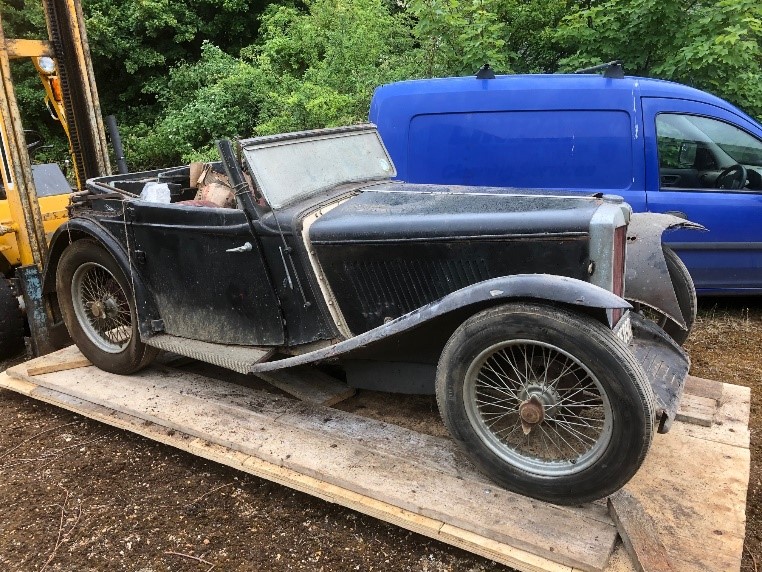
…………….and to close, this one has just been uncovered. Its old tax disc shows that it was last on the road in 1969.
The good news is that it will be rebuilt as a Tickford.
I used a Durite push on, push off switch no. 0-484-50, for the hazard warning switch from AGM Complete Parts & Components Solutions Ltd. This was installed on the dashboard edge, using a small bracket located near the steering column. Wire and terminals were from Vehicle Wiring Products Ltd.
Late TDs and the TF were fitted with a Lucas DB10 relay No. 33117. This relay substitutes the brake lamps with direction indicators on the side which is indicating, using the original rear brake lamps as indicators. It was probably wired this way to accommodate the current taken by the tungsten bulbs available at the time and to save wire. Now that the low current LED bulbs are easily obtained, a relay is not necessary. To use the relay and the original lamps would be a drain on the battery in hazard mode, as the relay takes about 1.5 amps per side. Using LEDs, the brake lamps can be switched from the brake lamp switch and the indicators directly from the dashpot indicators switch under the dashboard. The Lucas relay is not now used.
Many years ago, I restored my TD to original specification, retaining the Lucas relay and tungsten lamps; now, to install a hazard warning and to avoid complication, there is a need to update. To do this I will convert to LED lighting, not use the Lucas relay, and install new rear indicator lamps. An LED flasher unit will be necessary.
The brake lamps
To separate the brake lamps wiring from the direction indicator wiring, disconnect the wire from relay terminal no. 5 (green with purple) and join it with the wires removed from terminals 3 (white with purple), and 7 (white with brown). The brake lamps are now operated only by the brake light switch.
The rear indicators
Two extra wires are installed from the 33117relay location, to the new rear LH and RH direction indicator lamp units. Disconnect the wires from relay terminals 2 and 4 and connect these to the new feed to the LH rear indicator lamp. Disconnect the wires from relay terminals 6 and 8 and connect these to the feed to the new RH indicator lamp.
Remove the 12 feed to the indicator switch pole under the dash. This is from the main loom wiring and should be insulated. The L and R connections should remain.
Flasher unit connections:
Supply……………X Earth ………………E, or 31 Warning lamp……P Flasher out………….L
The Durite switch
The red indicator on the Durite switch has a screw thread. Make sure that this is screwed fully in.
The switch routes a 12v ignition feed to the flasher unit, but when operated it uses a direct battery feed. Referring to the Durite switch diagram…
For the 12v ignition circuit feed, disconnect the green wire at the flasher unit X (this is from the fuse A4) and extend to the Durite switch pin 1.
For the battery feed, extend from fuse terminal A2 to the Durite switch pin 2.
When operated, battery volts are fed to operate the flasher unit via pin 3.
When not operated, the original 12v feed from the ignition circuit, only, operates the flasher unit via pin 4.
Durite switch connections
Durite pin 1 fed from 12v ignition feed (green wire removed from flasher unit X). Durite pin 2 fed from 12v from battery fuse A2. Durite pin 3 (12v to flasher unit X, green) and to pin 4. Durite pin 4 from pin 3. Take the output from the flasher unit L and extend to Durite pin 5. Durite pin 5 further extended to the direction indicator switch pole. Durite pin 6 to the LH indicator switch terminal. Durite pin 7 to the RH indicator switch terminal.
Picture shows the Durite switch in-stalled in a TD. The small indicator next to it is a low oil pressure warning not yet connected.
The wiring diagram shows the wiring changes for the direction indicators in blue ink and those for the brake lights in red; also, the output of the flasher unit connected to the direction signal switch pole.
The sensor is a hydrostatic fuel sensor-made in the EU. It has four buttons, a trim potentiometer and an LED for calibration. Connection to the dashboard via a Molex connector (supplied). Connection to the ball valve via a brass pressure port.
The function of the buttons is:
Set gauge min Set gauge max Set level empty Set level full
An initial calibration may be carried out with a 1 ½ litre bottle of water on the bench. The details on this are given in the operating manual. Fuel density (DIN 228) is 720 to 775 kg/m3 or roughly ¾ the density of water. Therefore, 33cm water corresponds roughly to a full tank (43cm) of fuel.
Photo 1 – The sensor
The long, sought fuel level gauge for the T-Series cars is now available. This is a hydrostatic level sensor which connects into the fuel tank drain plug via a three-way ball valve. The installation of the ball valve adds a user-friendly drain facility. The arrangement at the bottom of the tank is shown in the drawing, which gives the installation detail.
2) The gauge (photos 2 and 3)
The sensor may be connected to a standard fuel gauge e.g. 240 … 33 Ohms empty to full. I have also tested it on a 10 … 90 Ohms empty to full. As the T-Series was never fitted with a fuel gauge, it was time for a reincarnation. The photos show cannibalized far eastern stepper motor 52mm gauges fitted with more period looking dial faces. The scale is non-linear in an attempt to compensate for the shape of the tank. (The red pointer was later painted).
Photo 2 – Matching colour for MG TD
Photo 3 – Black dial for MG TF
3) Connection
The gauge and the sensor require a +12V … 0V connection. This is not an issue on cars that have been converted to negative earth. On cars that have the original positive earth, it is easy enough to make an isolated floating negative earth supply via the switched ignition, using automotive relays. The details are shown on the cable harness wiring diagram provided. The actual length of cable required depends on the preferred routing of the cable. Approx. 4m (12ft) of cable harness is sufficient. The harness can be covered with polyester cable braid for protection. The corresponding Molex plugs and pins are included in the kit and will require crimping with a pliers. The wiring cable is not provided but specified. The recommended installation point for the gauge is on the dashboard to the left of the Speedo. On RHD cars obviously on the opposite side.
Installing this system as recommended does require carefully drilling a 52mm hole in the dashboard which is not what every owner wants to do.
Installation issues
When we tested the fuel gauge system, we found the sensor clogged, due to unknown rust in the tank. The drain plug is slightly lower than the gauze filter on the fuel line. If you suspect rust particles in your tank, although there is no flow, it may be advisable to fit an inline filter between gauge and sensor – see photo 4. This has been tested and should does not affect the hydrostatic pressure.
Make sure there is no air trapped in the fuel hose between the sensor and the ball valve. This will lead to false readings if not bled correctly. It is best to fill a little fuel in the tank then fill the hose and sensor with fuel in the vertical position, open the ball valve very slightly so fuel just drops out and into a bucket placed under the ball valve. Then quickly fit the hose to the ball valve. It is also recommended to keep the fuel hose as short as possible and no smoking!
Declan Burns Tel. +49 211 371529 [email protected] declan underscore burns at web dot de
Photo 4 – Installation with filter. The handle on the ball valve was removed on this installation(Photo courtesy of Klaus Harthof)
EXTRACTS From “AUTOSPORT” December 26,1952 and “ROAD and TRACK” December, 1953
“Autosport”
The Laystall Engineering Co. Ltd. have made available a special head, designed ab inito in high-compression form. It incorporates the larger valves and stronger springs normally supplied for ” Stage II ” tune, and these are included in the price of £48. It is cast in RR 50 aluminium alloy, which not only eases all the heat-flow problems, but saves 16 lbs. of weight. The main feature, however, is the scientific proportioning of the ports and head shape, which greatly increases the air flow. The technical side of the project is the work of John Lucas, who has put the speed into many of our fastest engines.
On the bench a b.h.p. increase of some 20 per cent is recorded, by simply changing cylinder heads, and making no other alterations to the engine. Bench tests are all very well, but it is road behaviour that really counts. Accordingly, I took over a TD type M.G. recently, to see if the theoretical advantages were obtained in practice.
It will be observed that, in the data panel, performance figures are given for the car in standard form and with the Laystall-Lucas head fitted. These results were secured at the M.I.R.A. proving ground, and were electrically timed. It will be realized that the length of run available did not allow the ultimate maximum speed to be developed, but the figures are strictly comparable.
The actual changing of the heads was done inside an hour and a half, or one and threequarters hours if one includes warming up and checking valve clearances. In order to accommodate the specially shaped ports, the Laystall-Lucas head is somewhat wider than the standard article. The regular manifolds and gaskets go straight on, however, and any normally competent owner could do the work himself. The M.G. engine is very accessible, so the job is quite straightforward.
I also used the M.G. as my normal hack for a few days, and the improvement in performance was most marked. Although the maximum speed is considerably augmented, it is the better acceleration in the middle ranges that one notices most in everyday driving. I used 80 octane fuel, on which the unit was remarkably flexible.
During my test, freezing temperatures were experienced most of the time, and I did not even cover the bonnet with a rug at night. Nevertheless, starting was rapid and certain every morning. The fuel consumption worked out at 28 m.p.g., but as this included the flat-out timed runs, I would say that a full 30 m.p.g. could be relied upon for ordinary journeys.
This head is applicable to the TB, TC, TD and 1 1/4-litre saloon model M.G.s, also the new Wolseley 4/44. It represents a remarkably cheap way of augmenting the performance, for it is ” ready tuned “, so to speak, and no work is entailed apart from fitting.
Pause, then, you sports car owners, before you cross swords with an innocent-looking M.G. It may have a Laystall-Lucas cylinder head under its bonnet, and you will be in for a rude awakening!
JOHN V. BOLSTER.
SPECIFICATION AND PERFORMANCEDATA AUTOSPORT TEST
Component Tested: Laystall-Lucas Cylinder Head, tested on TD type M.G. car. Price in U.K. £48, or £50
including fitting.
Material: RR 50 aluminium alloy, with valve inserts.
Valves: 36 mm. inlet, and 34 mm. exhaust valves, with 150 lb. springs.
Rocker Gear: Standard rockers and all other fitments.
Compression Ratio: 9.3 to 1.
Performance: 20 per cent. power increase.
Test Results: Standing figures are for last 100 ft. of 1/4 mile. Flying figures are for last 100ft. of 1,400yds.
Standard Iron Head, 1 1/4-in. S.U. carburetters, standing, 58.14 m.p.h.; flying, 70.79 m.p.h.
Laystall-Lucas Head, 11/2-in. S.U. carburetters, standing, 63.76 m.p.h.; flying, 76.52 m.p.h. Electrical timing, all figures are mean of runs in both directions.
Conditions: Snow, mud and ice.
“Road and Track”
Speaking of M.G. performance, we have been conducting some interesting tests on a stock TD. Space did not permit a full road test report this month, but as a brief preview, we found that the new Laystall-Lucas head (now available) added an honest 12 m.p.h. to the top speed and reduced acceleration time to 60 m.p.h. by over 5 seconds. It was quite an experience to watch the tachometer during the high-speed runs. We have to watch something to judge whether the car has reached terminal velocity. In this case, we kept going farther back each time, and the tach kept edging up during each timed run. Finally, it hit the peg (about 6,200 r.p.m.) and we watched the speedometer continue to climb from 90 to 95 before it stabilized. The best run was clocked at 89.10 m.p.h. with top and side curtains installed. Needless to say, we came away convinced that the Laystall head gives more than 20% added peak b.h.p. which they claim for it.
Sample Performance Figures
Stock M.G. TD Laystall-Equipped
0-60 24.2 secs. 18.0 secs.
Best top speed 77.6 m.p.h. 89.1 m.p.h.
(Timed Runs—Windshield Up—Driver and Passenger)
Editor’s note: The picture of the Laystall head, the extracts from Autosport and Road and Track and the advert for Cromard liners and pistons came from a brochure for the Laystall-Lucas head and Cromard liners which was kindly e-mailed to me by Paul Gent. I have re-typed the extracts from Autosport and Road and Track because the type face/font in the brochure is very small and some of us would need a good pair of reading glasses to study them.
In his covering note to me, Paul reckons that the Road and Track Test is the more convincing in some ways, although he points out that the text states that the Laystall head reduced the 0 to 60 time by over five seconds when the figures show over six!
I must say that I put an index finger over each eardrum (waiting for the bang!) when I saw the figure of 6,200 r.p.m. from, presumably, a stock engine.
And…….89.1 mph with two people on board – were they going downhill and was there an escape run-off to aid stopping?
Note the price of 48 GBP, which included the larger valves and stronger valve springs! The current price for the head with guides and valves is 1795 GBP (excluding VAT), 2154 GBP inclusive of VAT.
The writer of the Autosport test review, John V Bolster enjoyed a career as a racing driver, commentator and motoring journalist. He was well known for his “Bloody Mary” special – a twin engined JAP powered sprint and hill climb car that he built with his brother in 1929. It finally ran on methanol based fuel and Bolster is reported to have remarked that the car seemed to enjoy her alcohol as much as the owner does his!
Bolster raced at Donington, and other circuits in the 1930s and 1940s, but his motor racing career ended when he suffered serious injuries in a crash whilst driving Peter Bell’s ERA at Stowe in the 1949 British Grand Prix.
His racing career over, he took up broadcasting and served as Technical Editor of Autosport from 1950 to 1984.
From reading accounts of his life on the Internet it seems that he was a larger than life character; one snippet from a forum, which I took a special note of, because it appealed to my sense of humour, concerned Bolster’s reported ‘clarification’ (my interpretation) of the reason for the retirement of a works Ferrari in a race. The “official” reason for the retirement was “Electrical”; however, when Bolster reported on the problem, he said that the Ferrari retired due to electrical problems brought about when a piston exited the block and smashed the distributor.
Bolster died in Tunbridge Wells in 1984.
His memory lives on through the John Bolster Award for technical achievement. The is one of a series of awards presented annually by Autosport magazine. Previous winners have included Eddie Jordan (for achievements in motor racing) and Toto Wolff (for achievements with Mercedes AMG).
Mercedes AMG GmbH, commonly known as AMG, is the high-performance subsidiary of Daimler AG under Mercedes-Benz division. It independently hires engineers and contracts with manufacturers to customise Mercedes-Benz AMG vehicles.
I have read a number of very interesting articles on TC steering and the Bishop cam steering box over the years.
I hope this short article on setting up the drag link will help others to avoid the nightmare scenario of the drag link parting company with the Pitman arm (drop arm) as mine did on a left-hand bend some years ago – leaving me without any steering.
There are two points to consider when setting up the drag link. To ensure:
the peg in the steering box is in the middle of the worm when the wheels are in the straight-ahead position. (The point of minimum play)
there is sufficient rotational clearance on the drag link at each end of the steering travel. It was a failure to set this up properly that caused mine to “drop off” the Pitman arm.
Assembly
Before attempting to set up the drag link, ensure that both ends are in good order (the ball is not oval, etc.) and they are assembled correctly.
The N/S drag link end is identical to the track rod ends. Consisting (from left to right) of a dished screw end, dished plug and spring.
The ball fits between the screw and plug, and as for the track rod ends is fully tightened then backed off between ¼ and ½ turn before being locked in place by a split pin.
The O/S drag link end is different. This consists of four parts, (from left to right) the dished plug with a plain end, dished plug, spring, and screw with a plain end. On my drag link, this is different from the track rod ends in that it has only a single slot in it, rather than the two slots of the track rod end. Additionally, the slot cut into the body of the drag link end is longer. The screw is fully tightened and then backed off up to ½ turn as with the N/S drag link end.
When assembled, both the springs are on the O/S of the ball. This arrangement provides a spring “buffer” between the wheels and steering box for both left-hand and right-hand movement of the wheels.
Centralising the steering
Jack up the car under the centre of the front axle to maintain the springs in the fully loaded position and remove the N/S wheel.
Disconnect the steering box end of the drag link and loosen both the lock nuts.
Turn the steering wheel from one extreme to the other ensuring the peg hits the end worm in the box (sometimes the left-hand travel is restricted when the Pitman arm hits the sump). Counting the number of turns.
Turn the steering wheel back to its central position. (If unsure, remove the top cover from the steering box and check the position of the peg in the worm). A patient and willing volunteer is a useful “special tool” at this point to hold the steering wheel in position!
Reconnect the drag link and set the front wheels to the dead ahead position by rotating the drag link shaft to change its length. Like the track rod, the opposite ends have different handed threads.
When correctly set, tighten the lock nut on the steering box end and continue with the next stage. (At this point you no longer need your probably now very bored volunteer).
Setting the rotational clearance
The axis of rotation of the Pitman arm and the wheel on the king pin are different. To accommodate these differences the drag link is forced to rotate about its longitudinal axis as the steering moves from full left to full right lock. If the relative positions of the slots in the two drag link ends are not set correctly, then at one extreme the drag link ends will bind on the two steering balls, tending to twist the ball out of the drag link end.
Normally, there is insufficient clearance for the ball to “pop out” of the drag link end. However, over time both the ball and the drag link end will wear until, as with me, the drag link will twist itself of the ball – helped by gravity in the case of the O/S end. The wear was particularly evident on the slot in the O/S drag link and on the dished plug that fitted into the spring.
At this stage you can demonstrate this effect:
Fully tighten the lock nut on the O/S drag link end.
Go to the N/S of the car and twist the drag link full clockwise.
Twist the N/S link (wheel end) fully counter clockwise and pinch tighten the lock nut.
You will notice that as you turn the wheels in one direction the free rotational movement on the drag link will increase, while turning the wheels in the other direction will actually force the partially locked N/S end to turn on the shaft.
To properly set up the relative positions of the two drag link ends:
With the lock nut tightened on the O/S drag link end, pinch the N/S lock nut tight.
Move the steering to the extreme left and rotate the drag link back and forth until the outer casing hits the balls, noting the clearance.
Repeat with the steering at the extreme right.
Rotate the N/S drag link end on the shaft until the full left/full right clearances are approximately equal and fully tighten the lock nut.
Personally, I go through the above procedure a couple more times, probably more out of the fear of finding myself heading towards an oncoming vehicle rather than out of necessity.
Conclusion
The other components of my steering are in relatively good order and with the drag link set up as above, I can typically achieve about ½ to ¾ inch play in the steering wheel; I think that by TC standards this is acceptable.
I hope this article has not scared everybody into running out to the garage to check the clearances on their drag links, but considering the possible effect, I would recommend doing it.
Paul Ireland
Ed’s note: Publishing Paul’s article has given me the opportunity of showing a recently taken picture of his car (TC9701). His attention to detail in setting up the drag link has obviously paid off since he did the job a few years’ ago and he has covered thousands of miles in the car since then.
Tom Lange gives us an insight into the current state of the market for T-Series cars in the US.
Robert Lyell’s article in Issue 60 (June 2020) entitled “The current state of the market in the UK for our cars” provides a useful summary of the present-day market for T-series cars in the country of their manufacture. It may be interesting to compare the market from the other side of ‘the pond’, with a somewhat different perspective.
Broadly speaking, the values of US T-series cars are less than those in the UK.
Britain made absolutely no efforts to market the TA and TB models in the US, an automotive market that had very different expectations. Americans were used to large, roomy, smooth-riding (i.e. floating) 2-door, 4-door and station wagons (estates), and the market for small sports cars was almost non-existent, being limited to the very few individuals who raced – some TA cars had been privately imported for racing purposes. The diminutive Crosley Hot-Shot from the late 1940s, with its 724cc engine, stands alone as the only truly available American sports car, until the 1953 Corvette (and one would get a good deal of bluster about the un-sporting character of THAT car!).
When the TC was brought back to the US in some quantity by servicemen, it opened eyes as a car unlike anything hitherto available in the US – you have only to read Don Stanford’s The Red Car to understand what a revelation MGs were to those American drivers who were willing to try one. As a race car it was an immediate success, yet Abingdon made only feeble efforts to direct the TC’s EX-U model towards a US market, and only 494 of the total of 10,000 TCs were made with US characteristics, like bumpers. The TD was the first mass-produced British sports car available in numbers, as the majority were directed at the US in order to bolster the British economy with the US Dollar. Some 30,000 TDs were made, more than 20,000 of which came to the US as LHD cars.
Author, Lyell classifies “Supply” into three categories – concours, tidy and barn-find. Based on the American market, to these I would add Driver and Parts Car. To me, concours speaks for itself as a car that would win prizes and is therefore rarely driven. Tidy is a very nice car that anyone would be proud to bring along to a car show and it MIGHT win a prize. Driven is a car that is mechanically sound and regularly driven, but makes no claim to look splendid or be particularly original. Barn-find here refers to a car that has long been taken off the road and stored, needing everything. Parts Car is one that is probably too far gone to restore or is fragmentary, useful for parts only.
The US market seems to be divided into these categories:
Collectors and investors who want a superb example to admire (very few)
Dealers who are merely passing along someone else’s car in hopes of an unrealistic profit
Owners who regularly drive their cars long distances and who have mechanically upgraded engines, transmissions and/or suspensions
Happy owners (the majority)
Family members who are selling a deceased relative’s TD
Unfortunately, T-series’ brand value, film star and racing categories mentioned by Robert Lyell have very little impact in the US. The sad reality of it is that the US supply of T-series cars far exceeds the demand, to the point where prices have significantly dropped, especially in the past few years. Once upon a time TCs were THE car to have, and changed hands relatively seldom in the $25,000 range for a decent car. Even a barn-find was in the $18,000 range, rarely came on the market, and sold just as fast. Yet I now regularly see decent driving TCs for sale over here for less than $20,000, and know of a handful of runners that have sold at auction and privately for between $15-18,000. One UK dealer I know will not even consider buying a US TC for repatriation unless the cost is less than $10,000, and he does find them! A complete barn-find TC on eBay, up together and long-stored but a non-runner, got no bids at $15,000 recently, even though it was listed multiple times.
TF models have undergone an ugly-duckling-to-swan-change, from being viewed as the most temporary design step-children, to being sought after as handsome, refined and distinctive (especially the 1500 with the most powerful engine in the entire T-series range). With only 6,200 TF 1250s produced and 3,400 1500s, they have become much more desirable – an average driver TF 1250 will cost $15,000.
TD models appear to be growing like Edward Lear’s Manypeeplia Upsidownia plants! At any given time, there are at between 15 and 30 for sale on-line, ranging from dealer-high $35,000 to barn-find cars at $5,000, with rolling chassis at $1,500. If one adds cars listed in journals like The Sacred Octagon and Hemmings Motor News, the number no doubt doubles.
The majority of cars are in the $10,000 to $15,000 range, and would be classified as Tidy. Far more TDs are listed for sale than ever sell, despite being listed and re-listed – certainly not the dealer cars. The various VW-powered replicas, often listed as MGs, also do not sell…)
These MG prices appear to be somewhat below UK prices, so from that vantage point it might still be advantageous to bring a car over from America. But the exchange rate is not very strong, so it would be a lot of work for little gain. And then the car would probably need to be converted to RHD at additional expense.
Based on American valuations and desirability, we do have some differences in order with Robert Lyell’s model-by-model assessment:
TF1500: A 1500 for less than $15,000 in any condition is a bargain, if the original engine is in place. Over here, a 1500 block can sell for $3,000, while a show car can easily be $35,000. A nice TF 1500 will sell for every bit as much as a comparable TC, and perhaps more.
TC: Prices as noted previously. A quite acceptable TC is easily found in the $20-25,000 range.
TA: Fragile engines, and worth less with an XPAG, as many have fitted.
TB: Here in the US, TA and TB cars come up for sale rarely, and don’t yield more than a comparable TC – in fact, they are harder to sell. We have no racing community that is limited to pre-war cars.
TD/C (or Mark II TD): Worth perhaps $1,000 more than a standard TD.
TF1250: An average TF1250 is $12-15,000.
TD: TD owners may well feel slighted here, with their cars coming in last. To me, however, there is little question that they represent the best bargain: they are the most reliable and most easily worked on, parts are most available, and they are easiest to drive.
As the average age of T-series owners climbs steadily, it is unlikely that these MG values will rise any time soon.
MGT Repair is known for high quality T-series engine parts, including sets of brass core plugs, stainless steel thermostat housings, main cap and cylinder head studs and much more. I should also mention that he distributes Eaton-based supercharger kits and improved design TD/TF half shafts (originally known as Jerry Austin, and later, Dave Clark axles) - I might be needing a pair!
TC 3867 was built on 22 October 1947 and first registered on 5 November 1947. The engine number is over-stamped on the original plate with A 42352 indicating that a reconditioned engine was fitted late on during production.
JNA 362 spent its early years in and around Manchester and the North West before a stay in Devon and finally ending up in the North East. Initially green, the car was painted white and subsequently hand brushed red before a full red respray in 2005.
A comprehensive history file with the car shows that it was used initially as daily transport. However, as with many TCs, it took on a dual personality in the 1950s as a daily commuter during the week but used for motorsport at weekends. JNA 362 began competing in trials in the early 1950s, a DVD video shows the car being enthusiastically driven in the MGCC North West Trials in the early 1950s. During the fifties and sixties, the car went through a succession of owners in and around the Liverpool/Manchester area, its condition slowly deteriorating until it was bought in 1972 for £85.00 as a non-runner and went racing again with its first event being at Oulton Park in July 1976. There are photos of the car racing throughout the late seventies, including competing in the Curborough Sprint in August 1978. However, when subsequently sold in 1980 the car was laid-up for the next twenty-five years.
In 2003 the car was bought by an MG specialist where it underwent mechanical fettling before passing its MOT first time and being put back on the road for its first outing on New Year’s Day 2004 when it covered what was described as an uneventful 70 miles. The same specialist, when advertising the car for sale in March 2005, enthused that the car “featured extensively in magazines of the period and is now back exactly as it was when it was raced as a quick, well-engineered road car with various engine and other mods, a real time warp car”.
A new owner in March 2005 bought the car with the intention of a little light cosmetic work. This inevitably turned into a full restoration with new body tub, rewiring, re-chroming and a bare metal respray. However, after all this work the car was little used and was again laid up for another eight years to be subsequently bought by the current owner, Ian Forrester, in 2013.
The car was once again needing some work so Ian decided a light mechanical restoration was required to bring it back to full roadworthy condition but, as with these things, it soon became apparent that there was more to this than originally thought. Having stood for so many years, the suspension had sagged and the brakes were very poor; the car also leaked everywhere that it was possible to do so. The engine ran roughly and was unreliable making nasty noises if driven any length of time. The engine went through a number of head gaskets very quickly in the first two years of ownership and on one occasion the engine rear core plug burst showering very hot water over an unfortunate passenger’s feet.
Keen to retain as much of the racing configuration as possible, the engine was dismantled and rebuilt retaining much of the original bits. Unfortunately, this simply led to major reliability issues again and a well-known MG specialist was finally called upon to rebuild the engine to sort out the major problems of poor oil pressure and massive overheating. It seemed that the way the car was set up was good for racing but wasn’t good for modern road use.
During the rebuild it was found that the engine had been re-bored twice to 1350 cc and then 1410 cc. The head had been worked extensively providing very high compression and this was the cause of many of the problems. Consequently, to build in more reliability for the road, the head was swapped for a more standard unit with lesser compression and the exhaust manifold was treated to a ceramic coating to dissipate the engine heat more effectively. A new race exhaust was also fitted, the original having dropped off during testing! Other work saw modifications and upgrades throughout the car to provide reliability and comfort for touring.
Today the car retains its racing feel but is fully road legal. Completely reliable again after its second full restoration, it is quick and can keep up with modern traffic easily. Ian has tried to retain some of the patina and history in the car – the radiator shroud still has the scuff marks on either side from when the vehicle was towed at some point in the past – although the paintwork is still in excellent condition and a tribute to the painter who sprayed the car back in 2005. Driving the car is typically TC but accompanied by a crisp exhaust note. It is finally used and enjoyed as it should be by Ian whenever possible.
This website uses cookies to improve your experience. We'll assume you're ok with this, but you can opt-out if you wish. Cookie settingsACCEPT
Privacy & Cookies Policy
Privacy Overview
This website uses cookies to improve your experience while you navigate through the website. Out of these cookies, the cookies that are categorized as necessary are stored on your browser as they are essential for the working of basic functionalities of the website. We also use third-party cookies that help us analyze and understand how you use this website. These cookies will be stored in your browser only with your consent. You also have the option to opt-out of these cookies. But opting out of some of these cookies may have an effect on your browsing experience.
Necessary cookies are absolutely essential for the website to function properly. This category only includes cookies that ensures basic functionalities and security features of the website. These cookies do not store any personal information.
Any cookies that may not be particularly necessary for the website to function and is used specifically to collect user personal data via analytics, ads, other embedded contents are termed as non-necessary cookies. It is mandatory to procure user consent prior to running these cookies on your website.