Since the last issue we have been to Stoneleigh and enjoyed meeting friends, old and new.
The attendance seemed to be a little down on 2015; perhaps some did not attend this year due to past problems with queuing to get in and difficulty with parking. Nevertheless, we were kept busy virtually all day.
8.00am – all set up and ready to go!
We were pleased to have on sale Mike Harvey’s book entitled ‘Skinner’s Union’ (SU) and the author came to the stand after lunch to sign copies which had been sold. Fortunately, Mike brought along some more copies because by lunchtime we had sold the whole box allocated to us.
The level of interest in the book was high and there were many favourable comments about the quality of the offer and the reasonable price. A review of the book can be found later in this issue.
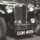
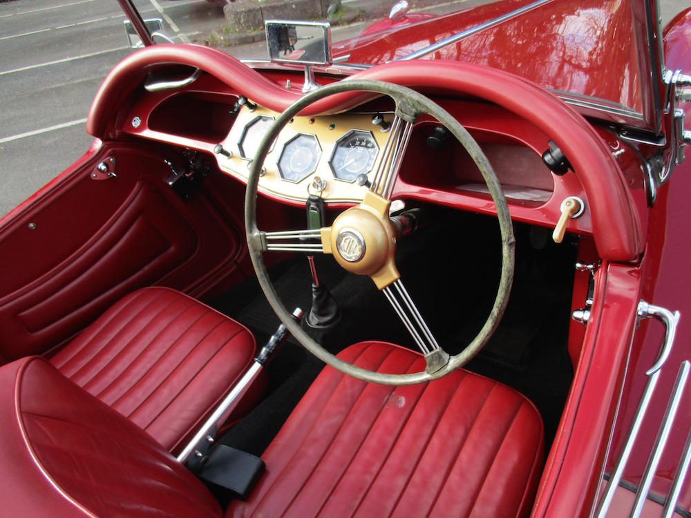
This issue’s front cover features Margaret Andrews’ 1955 TF1500 (TF9310) which is up for sale. Details from Margaret are as follows:
“Extremely rare original RHD TF1500, one of only 244 built for the Home market. Featured on front cover and inside Malcolm Green’s 1997 book ‘MG Sports Cars’ and the ‘Best of British’ MG video.
A very well-known car built to the highest standard and specification. First in Class Concours winner at 1994 Silverstone and other SE Region events.
Same owner since 1989 when it was bought as a barn find and fully restored over a five year period. Used and enjoyed for MG events, hill climbs and touring the UK and Continent.
Always kept in a dry garage and carefully maintained. Now has a nice patina. Less than 12,000 miles on the clock since rebuild.
As one of the last TF1500s built it was completed with revised components which were later fitted to the MGA including springs and shock absorbers. The engine is lightened and balanced with fast road cam, modified timing and distributor. It has an anti-roll bar and uprated MGA springs. New water pump fitted. 4 speed gearbox.
Offers around £35K – enquiries in the first instance to andrews.margaret(at)btinternet.com {please substitute @ for (at)}” (There are some more pictures of the car later in this issue).
Brooklands MG Era day is on 10th April. The 2016 event celebrates the 80th anniversary of the TA and the 55th anniversary of the Midget. events(at)brooklandsmuseum.com
Sandra Vinnell tells me that the MG Octagon Car Club ‘Founder’s Weekend’ (13th to 16th May) is almost fully booked. If you want to apply you’d better be quick! E-mail Sandra at Sandra.vinnell(at)btinternet.com {Please substitute @ for (at)}.
The TTT 2 Tour of The Forest of Dean and Wye Valley has been fully booked for some time and entry forms were sent out in January/February. Most of these have now been returned to me and next steps are to start planning the routes. We are expecting 40 cars on this Tour.
We are pleased to welcome Derek Holden and his wife Robin from Tasmania on the Tour. They will be arriving in a hire car but I hope it will be possible to accommodate them in any spare seats from solo Tour entrants on the Tour. If you feel able to offer a spare seat I’d be grateful if you would contact me.
Next year’s Tour which takes place on 18/19/20 August 2017 and based on the Chichester Park Hotel Chichester, West Sussex is already attracting interest. For 2018 I have a location in mind which I need to research further,
I am receiving more and more notifications of classic car events these days. I cannot possibly list them all but a couple of forthcoming ones are as follows:
The Rotary Club of Calne (Wiltshire) is organising an inaugural classic car Run on 22nd May. It starts from the town and covers a 52 mile route finishing at the Atwell-Wilson Motor Museum in Calne. Full details from calnerotaryclassicrun(at)gmail.com
There are Summer Fair & Classic Cars days on 4th and 5th June at the Observatory Science Centre, Herstmonceux, East Sussex. Details can be found at http://www.countrylifestylefairs.co.uk
Last but not least, the promised TTT 2 Index of Articles was available at Stoneleigh. A copy will be sent to printed copy subscribers with this issue. An electronic copy is available to download here.
JOHN JAMES
DISCLAIMER BY THE EDITOR
Totally T-Type 2 is produced totally on a voluntary basis and is available on the website www.ttypes.org on a totally FREE basis. Its primary purpose is to help T-Type owners through articles of a technical nature and point them in the direction of recommended service and spares suppliers. Articles are published in good faith but I cannot accept responsibility or legal liability and in respect of contents, liability is expressly disclaimed.
Purchased as much for the challenge and hopefully the satisfaction of its restoration, I always intended to panel the body tub and doors of TC 2628 myself.
My starting point was a new Ash frame, carefully aligned and bolted to a, by now, accurate chassis sitting in a reasonably well equipped workshop, including a 3 foot hand operated folder. I had read Michael Sherrell’s book, watched various helpful videos on YouTube and had some experience, having previously panelled a Caterham Seven, but that was 20 years ago.
Believing that sheet metal can only be cut, bent, stretched or shrunk, I decided to start with the front quarter panel to provide a gentle introduction to all four disciplines whilst I gained experience and confidence. Of course, being a relatively small panel, if it went wrong I could always scrap it and start again; fortunately I wouldn’t need to. My chosen material was Aluminium half hard grade 1.2mm thick. I purchased 2 sheets of 1m x 2m, sufficient for the whole job.
First I inspected the Ash frame, running a straight edge along the outer face of each timber, looking for any bumps or hollows; if there had been any bumps I would have removed them by hand block sanding. One small hollow was identified but not filled, instead it would be dealt with in the metal. I lightly sand anyway because it helps me to understand the shape and curves that I will need to persuade the aluminium to follow. I also filled the 2 rebates for the rubber door buffers with hard wood blocks to provide a continuous clean sharp edge.
The doors were hung and the gap measured, I had a consistent 6mm all round, which sounds generous but 2 layers of tight fitting Aluminium and a finisher would reduce it to a snug 2.6mm.
A paper pattern about 1 inch oversize, a little more where it goes under the scuttle and above the lower door hinge was used to cut out an Aluminium blank, using a nibbler to prevent any distortion.
Commencing with the vertical bulkhead fold, I decided to form this off the car as I considered the relatively thin and poorly supported Ash rail insufficiently rigid for use as a former. As the bulkhead front face is flat and the outer face close to a constant radius the resulting fold when curved should match the corner of the Ash.
I measured the angle with an adjustable square (much less than 90 degrees) placed the panel in the folder 1 inch from the edge and pulled it to the same angle, having now introduced stiffness to the panel, I marked a line a generous 11/16 inch from the outer edge of the fold and trimmed off the excess.
My technique is to use an old pair of Gilbow shears; aviation snips are fine for roughing out but I do not like the marks which the blade serrations leave. 11/16 was to ensure that the heads of the securing pins would be hidden by the second Ash frame when rebated and screwed to the front face.
Photo 01 – showing the rippling of the folded front face, later to be removed by annealing and slapping, as described in later text and shown in photo 03.
With the folded edge clamped to the front face in the middle I gradually pulled the panel with G clamps against a strip of 50mm x 9mm plywood on the outside until it touched the curved outer face from top to bottom. The Ash, checked by measurement, did not move; the inner corner of the Aluminium touched the Ash from top to bottom and the folded front face gently rippled.
My decision not to buy a shrinker based on high cost for little use was justified.
Before removing the clamps I also secured the panel to the Ash frame with 2 small wood screws so that upon each refit it would be in exactly the same place and during work it could not move; both are vital. One was through the excess material along the top edge under the scuttle screwing into the screen mount; the second in the excess material above the bottom door hinge screwing into the outer face of the vertical hinge rail.
Photo 02 – showing one of the small wood screws used to secure the panel to the ash frame.
The ripples were removed by annealing and slapping. Folding and rippling the edge has work hardened it, annealing by warming and allowing it to cool naturally will soften it back to its original condition; this can be repeated many times. Of course, insufficient temperature will have no effect and sadly too much will melt your hard work.
Removed from the Ash frame for fear of damaging the wood I apply a thin wipe of liquid soap and heat with the very tip of a welding torch flame so the (number 2) nozzle is about 4 inches from the metal. Heat until the soap turns brown, but only the area to be worked; leaving the folded edge cooler and therefore harder will help prevent it moving.
Once cool, the brown soap residue should be removed with thinners and a lot of rubbing.
Hitting metal against a hard face reduces its thickness causing it to expand, exactly the opposite of what we are trying to achieve. Slapping the peaks of the ripples with a wide flat face tool will compress them into the adjacent “valley” to increase the panel thickness and shrink the metal along its length, exactly what we need.
The Ash rail proved strong enough for this more gentle work, not difficult but there is a technique. The tool, often made from an old file which has been de-tempered, bent and ground smooth is also called a bumper or flipper. There is a certain satisfaction to making your own tools.
Carefully repositioned, the panel must be clamped as before, prior to slapping, to prevent any distortion of the outer face.
Photo 03 – ‘slapping’ to remove the ripples (look back at photo 01).
Next comes the bottom fold, with the panel repositioned using the 2 wood screws I clamped it tight against the substantial bottom rail and marked the corner onto the Aluminium. With the panel removed and laid flat it did not describe a straight line, indicating that it must be formed in situ. I cut the edge 11/16 inch beyond the line, repositioned and clamped the same plywood strip along its entire length as close as possible to the edge of the Ash. Then, avoiding the hollow, used a nylon headed mallet to move it 10/15 degrees just sufficient to reveal the fold edge.
My technique is to strike the Aluminium with the hammer head square to the panel in a glancing blow away from the fold to make the sharpest crease and almost pull the metal across. Simply hitting the edge will cause the outer face to buckle out away from the Ash, a difficult problem to correct.
I then removed the panel and continued the fold across the gap where the hollow occurred by positioning the panel between a flat work surface on its outside face and a 1 inch square steel bar on the inside so its sharp corner sat in the fold line at either end to bridge the gap. Tightly clamped the fold could be continued in the same way and to the same angle as on the car.
Photo 04 – showing panel removed and positioned between a flat work surface on its outside face and a 1 inch square steel bar on the inside.
As before, softened by annealing and replaced, the fold was increased to 45 degrees with the hollow treated in the same way off the car, annealed again and taken to 70 degrees; ripples started to form. A final anneal allowed the fold to be finished with a slapper until the ripples disappeared and the edge was tight against the Ash rail.
Being an early car, the door aperture treatment required only a simple fold, no welding. First step was to mark the edge of the wood onto the panel and cut 5/8 inch beyond it along the 2 straights and the gentle top curve but reduced to 7/16 inch around the 2 tight curves because the wider the fold the more difficult it is to stretch the metal without it splitting. Then I cut plywood templates for clamping the panel around each curve 1/8 inch outside of what would be the fold edge. Forming the fold was a repeat of the previous 4 stages but this time the technique is very different because the metal is being stretched.
Clamped hard and struck just inside the edge of each curved fold with the edge of a nylon hammer head will succeed in starting to shape the corner. The Aluminium will curve because it only stretches where it is hit. Do not be greedy, once the metal starts to move the panel must be removed and annealed, striking the second time a little further in and repeating until the striking point reaches the edge. The 2 straight folds can be treated in the same way as the lower edge fold described above.
For the short section of rear wheel arch I only folded the metal half way because in its finished form it will be folded over the additional thickness of the inner wheel arch.
The two lower external corners were simply finished by cutting, to form a neat edge to edge joint. Where the door aperture finishes at the top, I cut level with the bottom edge of the small additional wood block, with the panel side left sufficiently high to allow the scuttle top to overlap. At the lower door hinge I decided to manage the overlap with the rear panel by making a horizontal cut 1.2mm deep, level with the top of the hinge rebate and blending it out sufficient for the panel edge to sit into it.
Photo 05 – managing the overlap with the rear panel
Finally the door buffer notches were cut out with the panel in place using a junior hacksaw and square file, before marking out and drilling the holes for the panel securing pins.
For corrosion prevention in each area where the Aluminium panel touched the ash, I decided to key the surface with Scotch-Brite and paint with aerosol acid etch primer.
BOB LYELL
Ed’s Note: Thank you Bob for an interesting practical ‘how you did it’ article and I hope that it will be possible to have a follow up.
The fuel shut-off valve was illustrated in an old copy of TR Action magazine of the TR Register; it requires 12 volts to operate. I have added a safety relay which was recommended by the seller of the valve Tinley Tech Limited. 01767676181. www.tinleytech.co.uk
I have been assured by the manufacturer that the relay works with positive earth as long as the polarity of the connections are observed. I have not tried this on a positive earth system. Both the shut off valve and the relay are in insulated packaging.
The valve should be sited in a discrete position in the fuel line before the fuel pump in a position which gives access to the manual override lever. There is a direction of flow indication. Use connecting pipe which is compatible with modern fuel.
Because the valve could overheat when operating if no fuel flows, (if the ignition is on without the engine running) a relay which is triggered by pulses from the distributor side of the coil is used. A hidden switch can be inserted into the valve feed for additional security.
Note: It’s advisable to read these instructions completely before you begin disassembly. All the parts are identified in the photograph & legend below. Check to ensure that the two tabs on the Mazak lock body cover 5(b) aren’t broken. Be very careful, as these two tabs are unbelievably fragile! If the tabs are at all bent over at the back of the switch, it may be possible to very gently straighten them just enough to remove the cover. Great care must be used here! With one tab broken it can still be used but if both tabs are broken, unless the lock body cover is modified, the switch is toast!A soldering iron & a 6 BA spanner are the only tools required.
Prior to assembly ensure you have noted the OFF position on the body of the switch. The first F in OFF coincides perfectly with the projection in the body beside the single grub screw near the top of the switch. If using a decal it is necessary to complete this step before fitting the decal to ensure it is located correctly. Temporarily refitting just the face plate into its indents will ensure the decal is in the correct position. The decal supplied by “From The Frame Up” is a good reproduction of the original lettering however the artwork is fragile & the white lettering rubs off all too easily. I found it prudent to protect the lettering by spraying a coat of clear lacquer over the decal before applying it. Carefully examine the 3 tabs on the bezel face plate (12) as these are often damaged by PO’s who had no idea that the bezel simply untwists!
The phenolic insulator disc (10) with the four ears (not illustrated) may or may not be fitted. Later models saw this disc relocated to the small end of the large spring. Do not omit this insulator or smoke will be released! To assist in reassembly of an earlier switch such as the PLC2 it is suggested that the phenolic disc (10) with the 4 ears be replaced with the later disc (10a) & relocated. These insulating discs can be easily made from plastic ice cream containers.
The photograph and legend follow……
LEGEND
1
Switch Contact Bridge or Ignition Contact Ring
1(a)
Contact Ring Insulator (Note this is glued onto the contact ring)
1(b)
Small Insulator
2
Metal Contact Cover
3
Small spring
4
Cylinder Extension or bottom half of the Lock Barrel
4(a)
Brass spring loaded Pin & Cap
5
Cylinder or Barrel (MRN series TC & early TD only. FA series later TD)
5(b)
Hollow Lock Barrel or Mazak Lock Body Cover
8
Brass Contact Plate
10(a)
Large Insulator
12
Bezel or Face Plate (Note the bezel with the window is incorrect)
13
Knob or lever (Note horizontal black lever only. The 45 degree lever is incorrect)
14
U shaped Retainer
15
Keeper
17
Washer & 6 BA Nut (Note this has a 4 BA thread!)
(A) Examination of the (4) & (5) assembly will reveal a small brass button (4a) protruding from the lower part of the cylinder lock barrel (5) into a corresponding hole in the bottom half of the lock barrel (4). Depress the brass button (4a) to release the cylinder lock barrel (5) from the bottom half (4). Be careful not to lose the spring & brass pin (4a) as this is very easily done. Apply a little Vaseline internally to (4), (4a) & (5) as an aid to later reassembly.
(B) To reassemble the switch, first start with the key switch contact bridge, also known as the ignition contact ring (1). This is a small circular brass bridge with its arc shaped projections facing the bottom of the switch & with its axis in the one o’clock / seven o’clock position, when viewed from the front. Two insulated washers (1a) & (1b) then sit on top of it. Carefully place this assembly into the recess in the body, followed by the metal cover (2) with its projections also facing the bottom of the switch, then fit the small spring (3) large end first. Maintaining alignment, place the bottom half of the lock barrel (4), also known as the cylinder extension, into the body ensuring that the brass button recess is at 7 o’clock. Fit the fibroid fish paper & then secure it with a washer & nut (17) ensuring that it is not overtightened. This nut requires a 6BA spanner but has a 4BA thread! I made a tiny spanner from a small piece of 1/8” flat mild steel & an angle grinder. Next position the hollow lock barrel (5b), also known as the Mazak lock body cover, over the cylinder extension (4). It is essential that the deep cut out in the hollow lock barrel (5b) fits over the central molded stop in the body (7) & ensure that it doesn’t rock. Don’t bend the tabs on the lock body cover as this is unnecessary & will render the switch inoperable if they were both to break!
(C) Assemble the bezel face plate (12), the knob (13) and then the U shaped knob retainer (14). The cupped shaped keeper (15) slips over & secures the retainer (14). Note that the retainer (14) should be fitted first. The keeper (15) will have its convex side facing the back of the switch. On some switches I’ve dismantled, the positions of the keeper & retainer are reversed, which seems to have no effect on the operation. Next fit the phenolic insulator disc (10a) or a suitable replacement (See note). If a decal is used it must also be applied before (12), (13), (14) & (15) are assembled. The large spring should now be compressed & held with two thin wire twist ties opposite each other. I used multi strand copper household wiring however MIG wire can also be used. Place it in position, with the small end closest to the bezel (12). Next place the brass contact plate (8) over the 4 projections on the back of the knob (13) ensuring that the bumps on the plate (8) are facing you. Line them up with the corresponding 4 cutouts in the knob (13). It will be noted these projections & cutouts are different sizes & they will only fit together in one position. The assembled face plate is now complete. This method of assemblywith both springs compressed is much simpler than the 2 other methods I’m aware of & ensures that the mating of the two halves is straightforward.
(D) When offering the assembled face plate (12) to the switch body make sure the contact plate cutout (9) engages with & is centered on the molded stop in the body. This is what provides the stop for the 3 position lighting switch and prevents it from going too far clockwise or counterclockwise. Ensuring that the wire tails protrude from the slits in the body, gently press the two halves together. There is only one way the 3 tabs on the face plate bezel (12) will line up with the 3 notches in the rim of the switch body. Check to ensure the lettering on the bezel face plate (12) is properly aligned with the body of the switch. As noted above the OFF position should be observed on the switch body prior to disassembly. Take care not to rub off any of the decal lettering during reassembly. See the note on using clear lacquer.
(E) With the two halves of the whole assembly together so the 3 tabs have engaged with their notches, ensure that the face plate (12) is fully home. While maintaining slight, even pressure give the face a ½” counterclockwise twist so that the three bezel tabs now come to rest in their respective indents. It may be necessary to apply a little Vaseline to the lip as an aid to rotation. Place the key into the cylinder lock barrel (5) & insert the barrel into the switch ensuring that the letters are on the right & the numbers are on the left. Once engaged remove the key & the cylinder should remain. Gently untwist & pull on one leg of each of the two ties to remove them. This will release the tension on the large spring. Check the switch operation mechanically then secure the nut (17) with two 4 BA brass hex nuts, the second acting as a lock nut. 4 BA nuts with 6 BA bodies aren’t available & the use of solder just makes subsequent disassembly much more difficult than it needs be. Ensure that the nuts are not too tight.
It is essential that some insulating material such as fibroid fish paper electrical insulation (199-9620 from Element 14) be fitted under the nut to ensure that the nut & ignition terminal post are insulated from each other. Finally test the switch with an ohmmeter before installation.
There are a lot of urban myths re vintage valve train components, not necessarily well understood. As I am in process of rebuilding my XPAG, it seemed best to understand the dynamics of the valve train and its components (valves, springs, lifters, pushrods, etc.) in order to take advantage of modern performance and reliability related advances in design and materials that contribute to improving valve train stability. Valve train stability is the end game necessary to generate horsepower at higher RPM range when trying to improve reliability or performance. This discussion has been put together to consolidate previous, possibly disparate fragments of earlier information into one comprehensive discussion.
Remember:
Max HP: occurs at max engine airflow and max fuel burn at stoichiometric fuel air ratio.
Stoichiometric (in lay terms): the correct amount of a reactant, in this case fuel, to completely chemically react/burn with another reactant, in this case air, so there is no leftover residual unburned air fuel mixture remaining.
Max Torque: occurs at max unit air charge in the cylinder. This is best valve timing for max unit air charge.
Also remember, as vintage engines they need all the help available from modern technology to reduce unwanted stresses/wear from being introduced into the engine. Keep it alive for another 70 years!
1. LIFTERS: Many out dated myths revolve around premature lifter base wear with warnings to stick with OEM spring strengths, even to using only single outer spring(s). (This is a bad idea because the inner spring, wound in opposite direction of the outer spring, acts as a dampener mitigating harmonics of a single outer spring). Removing the inner spring and using only the outer spring should be limited to goal of reducing spring pressure on initial break in start up after a rebuild to avoid high point load scuffing damage potential between lifter base(s) and cam lobe in first few seconds of start-up. Vintage flat tappet auto engines traditionally used lifter bores marginally offset from being located under center of the cam lobe to generate the necessary lifter/pushrod rotation required, to more widely spread point loads of the cam lobe on the lifter base.
Confirm that lifters and their pushrods start to rotate immediately as engine is initially turned over without spark plugs installed, prior to break-in start up.
Lifter & cam lobe failure became an issue due to several reasons;
A) QC issues from lifter bore centers being located out of tolerance spec. when originally machined at Factory.
B) High Mileage, worn lifter bores, not addressed on rebuilds with bronze sleeves or oversize lifters. .010” oversize are available from Europe, under the County brand. (County is a major supplier to resellers of vintage parts, possibly now trading under a different name).
C) Poor QC chilled iron lifters or depth of case hardening/nitriding from various aftermarket sources. Note, that Moss outsources production of the lifters they offer. Two versions are offered:
i) One for OEM cams with OEM flat base lifters
ii) Some of the above are re-profiled to make the lifter base convex so they are compatible with modern Crane et. al. tapered lobe cams. Moss’s re-profiling, lauded as step in the right direction may reduce the thickness of the case hardening by “x” amount which could lead to premature lifter failure, also causing premature failure of cam lobe with things going downhill from there. Unknown if Moss has lifters re-hardened after crowning to regain full case hardening thickness.
D) EPA mandating reduced levels of ZDDP in engine oils to protect catalytic converters. Over time, aftermarket valve train suppliers started resolving the issues that were barriers to increasing spring pressures associated with lifter base & cam lobe wear. These new wear complications were limiting higher open valve spring pressures deemed necessary to gain horsepower via higher RPM. Reliable, wear free, road car flat lifters, with open spring loads of many hundreds of #’s, and open spring loads in race engines (700#-1000#+) are now common place, though the service life of springs is impacted as one moves to heavy duty race applications with higher seat and open spring pressures. I.e. moving to high cost, heavier roller cams, less stable valve train is not an end all solution.
EVOLUTION OF SOLUTIONS:
With worn lifter bores, accompanied by variations in tolerances of the bore center not being optimally offset from being under the Center of the cam lobe, and with reduced levels of anti-wear additives starting in mid to late 90s, premature wear began to occur on both chilled iron lifters, nitrided lifter bases and cam lobe. New solutions started to evolve as above causes were identified and understood. An interesting side issue is that wear reducing ZDDP additives were not introduced into motor oil ‘till after WWII. This begs the question of extent of flat lifter base & cam wear prior to introduction of these additives. As offset lifter bores were the pre WWII solution to wear, it seems likely that the lifter/cam lobe wear never became an issue as most cars from the 20s – early 40s had a very short shelf life & were ready to be junked at 30-40k miles. Henry Ford would send engineers out to auto scrap yards with instructions to inspect junked cars to see what parts were still in serviceable condition. He would then ‘dumb down’ these parts to save money. Clearly he was not a disciple of W.E Deming (the QC guru who is credited with turning around post WWII Japanese industry from producing “Jap Crap” to making quality products which would have a worldwide market).
1) Likely the 1st “fix” was to crown the base of the lifter a bit.
2) While this may have worked marginally as ZDDP levels were reduced, the next step was to further enhance lifter rotation by increasing the lifter crowning and also tapering the cam lobe laterally (side to side). With case hardened or chilled cast iron lifters, lifter failure still occurred when associated with low service life and especially heavy duty, higher spring open loads as EPA lowered ZDDP levels further.
3) Another more recent evolution to prevent wear at higher pressures, has been to use tool steel lifters that are hardened through & through to Rockwell 64. Should these lifters show signs of base erosion from dirt or pitting oxidation from moisture laden oil, they can have their crowned base(s) re-profiled indefinitely.
4) Most recently, for more extreme applications and to maximally extend service life, new lifters can be provided that are DLC coated, and can be expected to stop wear problems indefinitely. (Diamond Like Coatings),
These are for new steel cams, lifters, etc. & cannot be re-profiled without grinding through coating.
5) Additional current “work arounds” to provide more oil to lifter base cam lobe interface include:
a) An oil capture band around the middle of the lifter. Pressurized oil is presented through the lifter bore to the band where a cross drilling to the center of the lifter intersects a vertical drilling from base of lifter. The pressurized oil accumulated in the “band” is fed through drillings to the lifter base & cam interface.
b) This desirable feature, although not incorporated in the XPAG oiling system, can be replicated to an extent by broaching a slot in the lifter bore to gravity feed oil from the pushrod gallery to the lifter base/cam lobe interface.
c) Another recent solution revisits a 30s solution used in the Rolls Royce Merlin series of aircraft engines. A UK vendor is offering XPAG camshafts with an axial oil passage through the length of the cam. At each cam lobe there is a cross drilling to the central oil passage in the cam enabling direct pressurized lubrication to cam lobe lifter base interface. A system also used by Porsche on some engines for many years.
d)Moss 433-365 lifters for newish Crane cams with oversize core have incorporated elongated slots in lifter – see lines 54-77 of the link.
The TC Motoring Guild article http://www.tcmotoringguild.org/techinfo/TClinic-39.pdf includes some outdated & incorrect discussion. Mainly the omission of the evolution to laterally tapered cam lobes to further enhance lifter rotation.
Also, there is the assertion that .904” XPAG compatible aftermarket lifters are no longer available. Not so. There are many modern valve train suppliers that supply .904” solid and roller lifters for various Chrysler, Ford, & AMC engines. Some of today’s of today’s aftermarket valve train suppliers also offer modern crowned base, tool steel lifters hardened through & through. e.g. see http://trendperform.com/c-1149649-lifters-tappets.html
Ok, we are on the right trail, but of course, nothing is without issues that must be worked around!
1) These non-proprietary domestic aftermarket .904” lifters are shorter & considerably lighter than OEM XPAG lifters. The distance 1.88” (seat height) from the base of the lifter to the bottom of the lifter cup for the lower end of the pushrod is shorter. The XPAG lifter seat height is mol 2.122, i.e. .242” higher, enough that longer pushrods are needed. Also note that these shorter lifters weigh 84 gm compared to 94 gm for OEM XPAG lifters. (Note that new shorter push rods would also be required if a new cam with Crane style oversize core is used.). XPAG push rod lower ends are not compatible with the receiving socket in modern .904” non XPAG specific lifters, so new push rods are also required. This is works because Modern 5/16” push rods are significantly stiffer and stronger as they are chrome moly with .080” wall, and are rated stiffness (oscillation) stable to 350 hp @ 6000 rpm, a good thing & very desirable.
2) The last issue is that the top cup of current aftermarket push rods is not a match for the ball on the pushrod side of the XPAG rocker adjustor. However the Lifter Supplier advises that they could provide a top cup specific to XPAG adjustor screw 10mm ball.
After looking at various sources to upgrade the valve train, I am leaning toward Trend performance push rods: http://trendperform.com/c-1149673-push-rods-stocking-push-rods.html with a .080 wall chrome moly @$6.00 + ea. and .904 lifters, tool steel, heat treated through & through to Rockwell 64, Convex base lifters, micro polished, & suitable for cast iron cams.
@$ 17.11 ea. DLC coated + $65.00 ea. Bnz. lifter bore sleeves for worn .904” lifter bores are also available from Trend. Comparable lifters & p/rods available from Comp Cams, et. al.
Modern valves, desirable beehive valve springs, titanium spring retainers, etc are available from Ferrea, Supertech, Isky, Comp cams et. al.
Every gram saved in the valve train is a plus.
II SPRINGS
A) SPRING LOAD LIFE:
Springs going “soft”; spring wire has a finite fatigue load duty cycle life as they are exposed to high levels of cyclic stress. Over time, the fluctuating, cyclic twisting motion forces on the coil wire, stretching and relaxing the spring as it opens and closes can eventually fatigue fail the wire. If springs are losing installed pressure & go “soft,” the spring(s) have suffered plastic deformation, (failed in yield strength), or overheated beyond heat treatment limit. This occurs as fatigue inducing cyclic loads eventually exceed the yield strength (service life) of the coil wire. When the wire is stretched and its yield strength exceeded, plastic deformation stress levels are reached, the wire will not return to its original form, as the wire material has been stressed beyond its elastic yield limit. The installed spring pressure will be reduced at the installed spring height. Worse yet, over time the fluctuating cyclic forces stretching and relaxing the wire coil may cause the wire to break when the fatigue inducing cyclic stress forces exceed the UTS (Ultimate Tensile Strength) of the coil wire. The spring engineer’s task is to design the spring to operate within the predicted stresses to be encountered over its service life. Predicting spring fatigue life would be a function of determining dynamic loads involved, # of load cycles, & stress levels to be encountered. Design errors in this area could seriously affect the end-users’ pocketbook.
B) VALVE TRAIN DYNAMICS, HARMONICS;
Too complicated except for some generalities:
Basically; light weight, stiffness, low inertia on lifter and valve side of the valve train, along with most stable valve train possible is the end game. The service/fatigue life of the spring will be extended as the valve mass cycling the spring is reduced and the spring doesn’t have to work as hard.
Spring Surge; (The tendency of the spring to operate in & vibrate in an undesirable resonate condition). Springs and all components of the valve train that do not have infinite stiffness will vibrate, i.e. resonate in more than one direction and each at a different frequency. If a component harmonic coincides with other component frequencies, especially the spring/cam harmonic frequencies, the additional stresses can excite & add to surge causing spring to operate outside its design dynamic load capabilities, and fail. For instance, valve springs are held in place stable at their seat & retainer at top, as the middle of the spring is unsupported in column it can oscillate out of control, valve float is experienced and the valve head may hit piston.
III VALVES
In the past there have been dire warnings to avoid using stronger XPAG valve springs for fear of breaking valve heads off. Possibly this is true if these were aftermarket valves forged in a third world country by hand. Many current engines in daily drivers use valves with stems less than 6mm dia. & open spring pressures up to 200 plus psi. Virtually all motorcycles use valve stem diameters in the 4-5mm range at RPMs to 10-14k. Some with hollow heads (a practice introduced in aircraft engines pre WWII) & hollow stems. Valve headsbreak because the operating loads that valves are exposed to exceeded predicted stresses encountered.
All of the above is predicated on the assumption that the valve guides are not worn out of Spec; should the guides have excessive wear the valve stem may not translate in a perfect axial direction resulting in one edge of the valve impacting the seat under high load before the rest of the circumference of the valve face. This off axis point load could exceed design dynamic loads the valve stem was intended to cope with and actually break either the edge of the valve rim or the stem, especially if the valve has an undercut stem toward valve head.
For more detailed discussion of Valve Train Dynamics see:
Exhaust Valves: Modern Inconel & Nimonic alloy exhaust valves have basically eliminated “burnt” exhaust valve problems from exhaust manifold air leaks, or when using superchargers. No need for sodium filled valve stems, just leave stems & heads hollow to save weight. Also modern quality replacement valves have a .001” taper toward valve head to accommodate heat expansion into valve stem under valve head. As to future evolutions of valve train control w/o camshaft see:
WSH
TC 4926
01/01/16-10
Ed’s note:
This discussion paper by Bill Hyatt of Odessa, Florida, USA was recently published in the February 2016 issue of The Sacred Octagon, Since publication, Bill has revisited the text and has made a number of amendments.
In the June 2015 issue of TTT 2 I mentioned that Norman Verona had contacted me to say that he had found the TTT 2 website and that he had registered his newly acquired TC on the T-Database. He promised that he would send regular updates of a total restoration which he intended carrying out himself. The first update was published in the August 2015 issue of TTT 2, the second in the October 2015 issue, the third in the December 2015 issue and the fourth in the February 2016 issue. This is Norman’s fifth update.
WORK COMMENCES ON THE HOOD AND SIDE SCREENS
On the 17th November I took the radiator to a repairer in Angers, about an hour from where I live. I left it with them to repair. On the way back I called into the bodyshop and collected the hood and side screens as I have found a trimmer to repair them.
SOME DISAPPOINTING NEWS ABOUT THE RADIATOR CORE
Then I spent the afternoon washing the interior of the hood and the side screens. They came up reasonably clean except the two rear side screens which are the original canvas. The previous owner emailed me to inform me he fitted a new vinyl hood and front screens in the 1960s. At about 1700 the radiator man phoned to say the core wasn’t repairable as it had gone soft. A new core would cost 290€ or £202. Not too bad.
Hood and side screens. You can see the difference in the colours of the windows. The side screens (rear) are pink, not yellow. The rear window is yellow and cracked.
The material looks good now it’s been cleaned.
The front side screens are good, the windows are clear, but very brittle.
The rear side screens windows are pink not yellow as in this picture.
The rear window. It seems to have had a demister panel stuck to it. Remember them?
Ed: Yes, my Dad had one with his Morris 8 Series I (EMU 419)
The interior after cleaning with Vanish. I’m pleased, (which makes a change)
The newly painted grille refitted to the shell.
I have an optician’s appointment at 0830 on 19th November. This is not where you buy glasses but have a full eye examination and come away with a prescription if you need new glasses. So I have all the usual examinations with chin on a rest and instructions to “look at the cross” or “Regardez le croix”. I’m then shown into the optician’s room and we start by looking at letters in a mirror. I fail. Then he looks at my eyes through that brightly lit magnifying glass. After which he puts some drops in my eyes and I have to wait 15 minutes and have the back of my eyes photographed again. Back into the surgery where he looks again. Then tells me the problem is my eyes have swollen areas from diabetes and the cure is to have a sequence of injections into the eyes. I have to have 3 starting next Thursday and then in January and again in February. He also tells me that I shouldn’t drive.
So, why have I been working flat out for 6 months rebuilding a car only to be told I shouldn’t drive?
Anyway, never mind, I’ve been driving for the past 4 months and have got used to the poor vision so I’ll continue. “Shouldn’t” does not mean “mustn’t”.
On 25th November I removed the plugs and set the ignition timing to 0 TDC using an Ohmmeter. Then connected the battery and turned it over on the starter. I have oil coming up to the head but nothing coming out the rocker squirt holes. I’ve asked the supplier of the new pillars if they all have an oil feed or only one. If only one (or he’s not sure) I’ll take the rockers off and look.
This is a picture of the workshop as I left. It’s in darkness and this is the result of using the tiny, tiny, ickle flash on the camera.
On the 25th I was going to have a whole day off. However, by 1000 I was bored so brought the side screens and some tools into the house and started to remove the frames. Got most of the nuts off but a few were turning in the studs which are captive in the outside chrome strips. Got my Dremel but I’ve run out of cutting discs so that was as far as I could go.
First thing next morning I’m off to Brico for new Dremel cutting discs. Also bought some small rivets for the rear side screens, however, I think they may be too small. I also bought a strip of 300mm by 2mm metal to make a new end on one of the front side screen brackets which has broken at the end. Then I thought it would be a good idea to get a tin of rust killing grey metal primer. As I didn’t have a trolley I stuck the tin of paint under my arm. Queued at the checkout and when my turn came I put the discs, rivets, metal strip and 3 ali cases on offer for 23€ on the checkout counter. The girl, who I know, pointed at me and said something I didn’t understand. I thought she was pointing behind me so turned round to look at what it may be. She started laughing and lifted her arm. At this point I realised that the tin of paint was still under my arm. Oh, well getting senile!
I got back and set to work cutting off the last frame nuts. Drilled out the 12 rivets on the rear side screens and got told off because I hadn’t changed into working clothes.. An email from Roger Furneaux arrived in reply to mine about not getting oil to the valve gear. He explained the rocker shaft could only go in one way. Trust me, two choices and I pick the wrong one. I whipped the rocker shaft off, turn it round and refitted it. Two bolts were really hard to get in (the remade pillars have the holes drilled slightly offset) but I eventually got them all started. Pulled the rocker pillars down to the torque setting I found on the TABC site, which are different to the one printed in another document I have but can’t find. Anyway, torqued down and tappets set I turn the engine over on the starter. Still no oil. Then I notice the oil is running out of the two ends of the new shaft. Rummage around for the old shaft, remove the end blanking screws and fit them to the new shaft. This time I get oil to the tops of the rockers. Now, as I type this up I realise I forgot to turn the lock tabs over, so I’ll do that first thing in the morning.
Me, cutting the nuts off the frame screws. Please note the new very short haircut, I’ve not gone bald, only been shorn.
The blanking screw(s) in the old rocker shaft.
SUCCESS The oil coming out the rockers.
It’s so good I just had to take another picture. It’s oil, it’s beautiful, it’s wonderful, it’s marvellous, I’m beginning to break into song.
Nearly finished!
I’m hoping the radiator will be ready tomorrow. I’ll collect it from Angers and, in the Afternoon, paint the frames. Then Wednesday off to St Bruiec with the hood.
As I proof read this through, I remember where the document I’ve been using which has different torque settings for the rocker shaft pillar is. It’s on the scanner as I scanned in the list of spark plugs heat ranges for the TABC group. This document says they are 29 and 43 and the other says 16 and 33. Oh well, they’re tight and when I’ve turned the lock tabs up it’ll be OK.
On the 24th I started at 0900 by coating the side screen frames with rust remover. Whilst it was drying I removed the rocker cover and turned up the lock tabs on the rocker gear bolts and refitted the cover.
I then rubbed down the frames and welded the one that had fractured and then made a piece for the broken bracket and welded that on. Having done that, I then painted all four frames with rust killing primer (the one that I keep under my arm!). Lunch!
I’m not sure why I’m spending so much time on the hood and side screens, they’ll probably never get used. But, having taken all the time and trouble I’ve taken so far, may as well do the whole job. Which reminds me, I wonder how much labour I’ve spent so far – hang on and I’ll do some working out………….
Hang on, calculator is buzzing…….
Nearly there!
OK, I reckon I’ve worked on the car for 121 days. I’ve not counted the time the family were here or the ten days I had off. So, assume I averaged an 8 hour day that gives us 968 hours. So below is the
cost at different rates.
968 at £25 ph = £24,200
968 at £35 ph = £33,880
968 at £50 ph = £48,400
I won’t go on. it’s a lot of money even at £25 per hour. Add to this about £35,000 on parts, consumables and tools and the real cost of renovation would be £57,200 so far. Probably another £6,000 to add when the bodywork is finished.
If anyone wants to make me an offer of £65,000 I may consider it….. What? No offers, oh well I’ll just keep it then.
Next day (26th) I collect repaired radiator. Looks good.
The radiator. I know it’s sideways. You can lay down to look at but it’s still a rad.
We’re off to St Bruiac tomorrow to take the hood and side screens to the boatyard place. Then to a nice restaurant for lunch.
It’s 0700 on the 26th and I’m going to have needles stuck in my eyes. I’m really looking forward to this (why is my nose getting longer). I’ll report back later. One thing is that my darling wife has banned me from the garage until at least Monday in case I get an infection in my eyes. So, I’ll be laying the new tiles in the bathroom, something I was supposed to do last year!
Whilst I’m waiting for my darling wife to get dressed I’ll publish the picture of my box spanners. Don’t get too excited, I know it’s very sexy, but keep control.
Box spanners. They fit the starter motor bolts just lovely.
UPDATE:
The nurse put loads of anaesthetic drops into my eyes as well as an anti-septic. Then the doctor (or whatever he’s called) tells me to look down and puts the needle in the right eye. I thought this is OK, I can’t feel anything…… then he injects and it’s painful. He then does the other eye. I didn’t feel too good after this trauma. We go home, Lynne driving and I sit down, put the radio on and close my eyes which feel very sore. It’s now 1700 and the soreness has worn off and, apart from a big black blob floating around my right eye, I feel OK.
The big problem is they have said I shouldn’t do anything which could get something in my eye as infection is the main risk. And this doing nothing is for the next 15 days! No work on the car or laying tiles then. I’m going to the doctor on Monday (for a prescription, no repeats here, you must be examined every 3 months) and will ask him.
In the meantime, I’ve been searching for an original tool kit and bought most from different sources.
Tools, wonderful tools!
It was now 1530 on 28th here Final Score was on the BBC red button. So I settled down to watch the scores come in. When the games were finished I checked my emails and looked on FB…… my son had pm’d me with a photograph of the missing headlamps. My daughter had, by mistake, left them in the office when she brought the tub and all the other stuff I’d had sent to the office over the previous few months. When we had the vans back-to-back in the hotel car park in Portsmouth (1st August) I was about to open a package which I assumed was the new headlights. They all shouted at me to leave it for now as they wanted to go in to the bar. I therefore assumed the headlights were in the van but couldn’t find them when we got back. I’d dropped the tub and body panels at the bodyshop on the way home so spent ages searching the workshop, the house and the bodyshop for them. They were in the office all the time and my son found them as he’s moving offices over the weekend.
What a result! a mystery solved; I hate mysteries, and I now have a pair of new unused headlamps for sale. So I send an email round to the TABC group offering them at, about £150 less than retail. Within 10 minutes they’re sold. I am having a good day.
The horn with chrome effect paint on the centre nut.
The headlights. These are the replacements but will be the same as those now found which are in Sheffield. Sounds like Tolkien, “the light that was lost and now found”
This takes us to the end of November. Only worked a few days in December as I had some sort of virus and then it was Christmas. So I’ll combine December and January in the next instalment.
You can read the whole blog on www.frenchblat.com. Click on MG TC at the bottom left.
There are a number of techniques of non-destructive testing:
Ultrasonic
X-Ray
Magnetic Particle (Magnaflux)
Dye Penetrant
All have their uses and limitations, but for the home user the Dye Penetrant technique is the easiest and at £30 plus VAT the cheapest. I used Ardrox 996PB. I had seen similar used in the Fleet Air Arm in the 1970s and 1980s.
There are three parts to the kit which comes in aerosols.
Cleaner
Red Dye
Aqueous Developer
My first test was on the Stub axles. The machining on mine is fairly rough which I thought would affect the results of the test, however this was not the case. Difficult though to see a crack with the Mk1 Eyeball.
Step 1:
Thoroughly clean the item with the Dye remover Ardrox 9PR5, then clean it again!
Step 2:
Spray it with Ardrox 996PB and let it stand for a while
Step 3:
Clean it off with a rag moistened with the Dye remover. Do warn your friends and family that you are using this as it looks as though you have cut yourself badly. On the other hand you can play childish pranks! However read the directions as there are dire warnings on bare skin contact and the need for well ventilated spaces.
Step 4:
Spray on the developer Ardrox 9D1B. This is a water based developer that dries to a white powder. The kit I have got seems to take a lot longer to dry than I recall, but we were using it in the Mediterranean at the time. I also put on two coats.
Step 5:
Make a cup of tea as you need to leave it for 20 to 30 minutes for the dye to leach out into the developer. You are looking for a sharp red line and then as time passes it will turn into a dull stain as it leaches further. The pink spots indicate porosity or the turning marks shown the first photograph. No cracks though.
It may be worth breaking an old tile and putting the pieces together with tape to test a known crack to see how the system works. Now, are there any volunteers to polish my stub axles?
Tim Parrott
tp(at)tpss.co.uk {please substitute @ for (at)}
Ed’s note: Tim is rebuilding TA2664 and has sent me some ‘House of Horrors’ pictures, one of which is reproduced below. Tim describes it as “a new approach to wiring”.
He’s also found, to name but a few bodges: Bolts instead of brake bleed nipples on the front brakes; engine journals and big ends missing split pins; only 6 bolts holding the sump on (remaining holes had damaged threads).
The Douglas Bader TA – The article in the last issue has generated a lot of interest.
• Peter Bird, noting the comment that the car may have been modified to enable Bader to drive it more easily, e-mailed as follows:
“My father, who had worked at Jarvis of Wimbledon as a mechanic before the war was stationed at Tangmere at the same time as Bader and because of his experience with MGs worked on the car and drove it on a number of occasions. Apparently the brake and clutch pedals were transposed to suit Bader’s artificial legs. This made driving difficult and my father claimed that he could only drive it with his legs crossed. It would be interesting to know whether anyone else can confirm this”.
• Rob Dunsterville from Forster, New South Wales e-mailed with the following:
“I had correspondence with a chap who worked with one of the dealers in South London when I was researching my Jarvis story and he mentioned seeing the Bader VA but I can’t remember him saying anything about the TA. Didn’t he start with a J2? (Ed: Yes!) The VA was bought before the end of the war by his wife and she had the controls altered so that the car was ready when he got back from being a POW”.
• John Gripton of Red Wells, London Road, ASCOT e-mailed to advise me that his house is actually in Sunninghill, ASCOT, so my reference to Bader having possibly moved later to Sunninghill from Red Wells was incorrect. It’s one and the same place!
New stub axles for TA/TB/TC
Tim Patchett (T-racer) has arranged for another batch of stub axles. The price is £675.00 per pair, plus carriage.
Please contact Tim for full details: happypeople222(at)gmail.com {please substitute @ for (at)}.
Classic Car Paintings – I have received the following from artist, Alan Denning:
I have a passion for classic cars and I also paint mostly using water colours. Just recently I have combined the two, please take a look at my new web site www.alansart.co.uk
Here you will see a selection of my water colour paintings. These were all painted from photos I have taken at classic car meetings or car museums. If you or any of your members would like me to paint a water colour of their classic car please click the link in the top right hand corner of my web page and it will suggest what to do next.
Repair of Clocks – John Thompson has contacted me to say that he is happy to add his name to those of others who have received excellent service on the repair of clocks by David Ward. John’s clock in his TF was successfully repaired by David,
For those who are looking to have their clocks repaired, David can be contacted on: warddavid(at)virginmedia.com {please substitute @ for (at)}
Hagerty International Insurance – I have recently received a couple of bouquets about Hagerty’s competitive quotations and their service as follows:
• The first was from an owner with a fleet of six classic vehicles, who said:
I am progressively moving my 6 classic vehicles over to them. They are so helpful and the prices are great. I am going to have all 6 vehicles on one policy by the time 12 months has rolled round – what a time saver! Of course, you never know with insurance until you make a claim but so far I’m hooked on Hagerty’s service.
• The second was from an owner who has insured two classic vehicles with them, one of which is a T-Type:
Genuine and straight forward just as it should be. Impressed!
Both owners obtained quotations using the promotional code: CCTTT.
Talk and Film Show at Albury Village Hall (nr Ware, Hertfordshire) on 7th May.
TTT 2 member and subscriber, Richard Hinton has e-mailed with details of the above event.
Richard is a member of a group of lifelong motor racing enthusiasts drawn from all corners of the country, many of whom have been competitors themselves or worked in some branch of motor sport or the industry.
Three times a year the group runs “History of Motor Racing” film shows with a guest speaker at Albury village hall (between Ware and Bishops Stortford, in Herts). The next film show talk day is on 7th May and is devoted to all things MG.
Richard would like to welcome owners of T–Types, Triple-Ms and later models to bring their cars and park them on the lawns of the village hall for this all day event.
On offer is morning coffee, a 2 course barbecue lunch, afternoon tea and cakes, lunchtime quiz, 3 hours of films and well known guest speakers, Mike Allison, Graham Robson and Peter Browning.
All this for £30 for this non-profit making event.
If you would like to register an interest, please e-mail Richard at richard(at)hinton1.fsbusiness.co.uk {Substitute @ for (at)} and he will put you on his e-mail newsletter database which will ensure that you receive all notifications and news as soon as bookings open.
DVLA representative for the MG Octagon Car Club
Some of you will know that I process applications for reclaimed and age-related registration marks for the MG Octagon Car Club. As a Club member I do this work on a voluntary basis.
If you would like to avail yourself of this service the fee is a modest £25 for Club members and £50 for non-members and dealers. The DVLA fee is currently £55 for age-related applications (there is no fee for reclaimed registration mark applications).
My contact details are jj(at)octagon.fsbusiness.co.uk {please substitute @ for (at)} or phone 0117 986 4224. It’s best to e-mail brief details or phone first before proceeding with an application.
Business was brisk in 2015 (my first year of doing the job) with nearly 50 applications processed.
I recently received a letter from a private business individual offering this service for an average total fee of around £200 to £250!
Totally T-Type 2 – Issue 36 – June 2016
The next issue is due out around about 15th May and will include some items which have been held over from this issue. This will include:
• An article from Frans Sitton on his TF rebuild
• Some words of wisdom from Steve Cameron entitled “Right to the Core”
• Another instalment from Norman Verona on his TC rebuild
• An article from Ian Linton on fitting a low oil pressure switch for his MPJG engine
• An article entitled “Oil Circuit Improvement” from Laurent Castel.
Credit is due to Mike Harvey for producing a fascinating history of the SU Company and its products and the more prominent members of the Skinner family associated with the business.
The book runs to over 300 pages with more than 85 period photographs and nearly 50 drawings and illustrations, including a good few period advertisements.
The early history of the Skinner family is covered in detail. Their involvement in the large national footwear company of Lilley & Skinner generated the family’s wealth and helped to keep the SU Company afloat during the difficult trading years between 1919 and 1926 prior to it being purchased by William Morris in December 1926.
The Skinner Family involvement with carburetters started as early as 1900 when George Herbert (Bert) Skinner and his younger brother Thomas Carlyle (Carl) Skinner began experimenting with fuel mixture and atomisation. This led to the building of a prototype carburetter in 1904 by Harry Mooring at George Wailes & Co. and later (1908) the manufacture by the same company of Bert Skinner’s patented design of constant depression carburetter under the control of Carl Skinner. Later, on 22nd August 1910, The SU Company Ltd was formed with the SU brand initially still manufactured by George Wailes & Co.
Two chapters of the book cover the successful hillclimbing and sprinting activities of Carl’s son Peter, and daughter Barbara, and the four ‘Skinner specials’ whilst subsequent chapters cover SU Aero Carburetters and Pre-War expansion and Post-War changes.
There is an unbelievable amount of information and detail in this book – a selection of the relevant patents (1906-1926); SU vehicle products in chronological order (1904-1994) and SU aero-carburetters (1909-1944).
A book you’ll find hard to put down once you’ve started to read it. Exceptional value at £20 plus ‘P&P’.
Visit www.sucarb.co.uk or phone 01722 412500 to purchase a copy – ‘Part Number’ ALT 9527.
This website uses cookies to improve your experience. We'll assume you're ok with this, but you can opt-out if you wish. Cookie settingsACCEPT
Privacy & Cookies Policy
Privacy Overview
This website uses cookies to improve your experience while you navigate through the website. Out of these cookies, the cookies that are categorized as necessary are stored on your browser as they are essential for the working of basic functionalities of the website. We also use third-party cookies that help us analyze and understand how you use this website. These cookies will be stored in your browser only with your consent. You also have the option to opt-out of these cookies. But opting out of some of these cookies may have an effect on your browsing experience.
Necessary cookies are absolutely essential for the website to function properly. This category only includes cookies that ensures basic functionalities and security features of the website. These cookies do not store any personal information.
Any cookies that may not be particularly necessary for the website to function and is used specifically to collect user personal data via analytics, ads, other embedded contents are termed as non-necessary cookies. It is mandatory to procure user consent prior to running these cookies on your website.