
The side screen box is a part of the rear centre panel which is bolted to the body chassis frame and forms the rear support bolted to rear chassis mounting point. It is imperative that the differential cover that connects to the rear centre panel is horizontal or the doors will not fit correctly as the rear body pillar to which the door is fixed will not be vertical. Additionally, the rear centre panel needs to be at 3 deg from the vertical sloping forwards while the front edge of the side screen box should be vertical.
The sides of the side screen box need to reflect the required angles to ensure that the rear of the car is correctly aligned. The drawings of these in various documents show a simple shape that does not make allowance for the angle of the rear centre panel or the rear bottom rail through which the rear section is attached to the chassis.
A new side curtain compartment was bought as the one installed was not the correct size and had been fabricated when the car was last rebuilt in South Africa.
The replacement was not of very good quality but was the best available at the time.


Checking the dimensions, I found that the bottom upstand to which the rear centre panel is fixed is ½” whereas it should be 1”. If the main fixing screws were to pass through this they would only be 3/16” from the edge of the rear centre panel, which would not be sufficient to carry the weight of the rear of the tub. Additionally, the top return that connects to the differential cover is also ½” and should be ¾”.
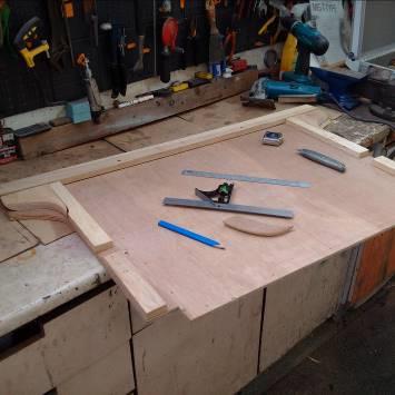
The side screen sides I made to the dimension shown in a reference book did not fit correctly in the side curtain compartment.


To ensure that the rear of the tub locates on the chassis correctly these were discarded and new ones made. I drew up plans taking in to account the required 3 deg angle of the rear centre panel and the vertical front edge of the side screen box.


Once cut and before finishing, I checked the size and angles against the side screen compartment.


I then checked the angles against the rear centre panel and that the fixing holes that I had already drilled in the rear centre panel lined up with the side panels.


The top of the side screen box sides form the supports of the side screen box top that fits between these and the rear top rail. I clamped the top rail in place and checked that all components that make up the assembly fitted correctly.


Once loosely assembled, I positioned it in the jig to check that it would fit correctly. I found that the front of the side curtain compartment was higher than it should be by ¼” and it needed to be re-bent taking this in to account.


I straightened the return while being careful to maintain the 3 deg kink 1” below the return then re- bent the compartment top return to give a ¾” lip that connects on the differential cover frame.


The side screen compartment requires holes being drilled in the edges for fixings. In addition, the compartment rests on the chassis at the rear mounting point and bolts pass through it and the bottom rear rail to secure the rear centre panel assembly.


These holes would normally be slotted to allow for adjustment during mass production, however I was able to place the holes where required for this chassis to further strengthen the assembly.
Taking the dimensions from a reference book checked against the various components that I had pre-drilled and the TC specification book that gives size and location of all the screws used in the tub.


Having drilled all the holes, I sprayed the compartment with galvanizing paint to provide protection as it is located adjacent to the rear wheels and will be subject to water spray.


It took three attempts to get the side screen box sides correct, the first as I used dimensions from a book, the second because I used the side screen box compartment which was wrong.


Once the holes had been corrected, the rear centre panel needed to be grooved to accept the rear panel and the rear quarter panels, these were marked out ready for cutting.


Before using the router, I decided to check all other dimensions of the rear panel assembly and side screen box.


Once checked, I used a router to put the groove in the rear centre panel.


I then fitted the corner bracket and the upper and lower side brackets.


Roughly shaped the ends to curve round and mate with the rear quarter panels.


Sprayed the side screen compartment with black stone chip before installing in the jig.


Next, I checked that the inner wing to rear body centre panel fit and curve radius was correct.


This is a complex curve and I was happy with the fit so proceeded with the assembly of the side screen box and rear centre panel. I will be assembling all the timbers on the jig with half size screws and only when satisfied that everything is correct will these be changed to the correct screws a joint at a time. This will be done on the jig.

First the rear centre panel was bolted to the body chassis frame and positioned roughly to give the 3-degree rake towards the front of the car.
Next, the side screen compartment was positioned under the centre panel and the side screen side placed between the centre panel and the side screen compartment.


Next, I screwed the side screen compartment to the diff cover frame and fixed the frame to the body chassis frame.


I then levelled the jig and body chassis frame such that the diff cover is horizontal, the rear centre panel is at 3 degrees and the side screen box sides are vertical.


I screwed the panels together with half size screws and only every second one to hold it together while the rest of the tub is assembled.

Once installed it can be seen that the side screen box sides need to be an irregular pentagon which is a complex shape taking in to account the rake of the rear centre panel so the side screen compartment bottom is horizontal and meets the chassis at the correct angle while setting the side screen compartment top horizontally.


The side screen box assembly is now complete other than trim pieces that will be added once the inner wheel arches and rear wheel arch timbers are in place. The body chassis frame is bolted to the chassis at 6 points, two at the front, two at the middle and two at the rear through the side screen box bottom rail. The height of this needs to be adjusted when installed on the chassis to adjust the rear door pillar which must be vertical or the door will not close correctly.
Paul Rutherford
Hi Paul, really appreciated your article which has been very helpful to me as I am rebuilding the side screen box just now. One question please (maybe obvious!) …at the bottom of the metal box there is a 15mm upstand, does this go outside of the rear plywood panel, looks like it does in your photos, if so does this not allow rain water to get in..I can’t quite make out that detail. My TC does not have a metal panel covering the plywood behind the fuel tank, don’t think there is one? Regards, Phillip