
Paul Ireland has come up with an improved design over the original Factory arrangement.
When I bought my TC in 1967 it looked as if the pedal bearings had not been lubricated since the car had left the factory. The clutch pedal had seized onto the shaft and a very rusty shaft had been rotating in the pedal box and worn both and the central and outer supports! I have been running for the past 46 years with a bodge shim and wobbly peddles! At the time I also drilled and tapped the pedals and fitted grease nipples. This worked fine, but meant you had to crawl under the car to grease them. 46 years later this is becoming more difficult. This year I decided it was time to fix the problem by fitting an oversized and cross drilled shaft so I could grease the bearings from the outside of the car.
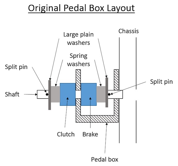
The pedal box is basically a U shaped fitting with two 5/8” holes to mount the pedal shaft. It is fitted onto the chassis with three bolts and one rivet (I do not know why the factory fitted one rivet) which means it is very difficult to remove. There is a larger diameter hole through both the outer and box sections in the chassis. There are a number of problems with this arrangement:
• There is no means to lubricate the pedals.
• Shaft can rotate in the pedal box and wear the pedal box (as mine did).
• There is no means of preventing end float in the shaft; it is only located by the two spring washers.
• Spring washers allow dirt and water to enter the ends of the pedal bearings.
• Clutch end of the shaft is unsupported at one end placing a high load on the outer (chassis end) pedal box support.
• It is not possible to provide for a grease nipple as the outer split pin prevents drilling an end feed.
My replacement shaft attempts to address some of these issues.
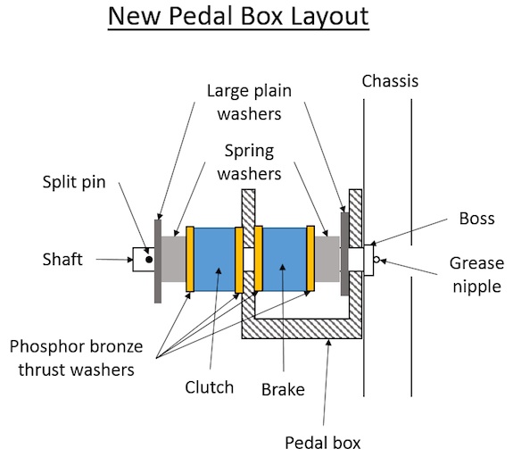
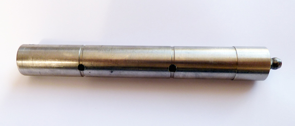
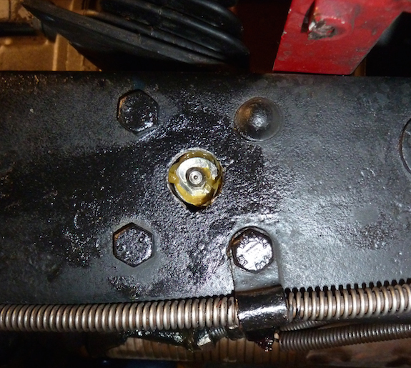
The boss on the outside serves to provide an end location for the shaft and removes the need for the inner split pin. The outer part of the shaft is +2 thou to create an interference fit with the outside of the pedal box to prevent the shaft from rotating. This arrangement has allowed a central feed hole from a grease nipple at the end of the shaft to cross drillings inside the pedal bushes. This permits the pedals to be greased from the outside of the chassis. In addition I have added 4 phosphor bronze thrust washers both to “seal” the faces of the sides of the pedals to deter water and dirt ingress and provide a bearing surface.
The new shaft was made from 18mm stainless bar and I increased the diameter of the pedal shaft by 55 thou (from 625 to 680 thou) to allow for the wear in the outer side of the pedal box. To maintain the thickness of the bushes in the pedals, I also reamed the pedals to increase the diameter of the hole in them by a similar amount. The new oversized bushes and thrust washers were turned from phosphor bronze.
The thrust washers were made after the central hole had been bored to fit the new shaft by facing the bar and using a parting tool to slice off each washer, repeated 4 times. The inner washers are 60 thou thick and the outer 75 thou. Each washer has 4 filed radial groves on one face, deeper on the inner edge tapering to nothing on the outer to allow grease to flow between the pedal and washer. They are a close fit on the shaft to force grease between the pedal and washer rather than allowing it to flow between the washer and shaft.
The accuracy of the cross drilling is not critical as long as the two grease feed holes meet the central feed. At the brake pedal side, the plain and thrust washer thicknesses should be chosen to ensure there is adequate compression of the spring washer.
The distance of the split pin hole from the end of the shaft depends on the thickness of the plain and thrust washers and again should be positioned to ensure the spring washer is adequately compressed. The split pin hole is at 90o to the grease feed holes to ensure the bearing face under load is properly lubricated when the split pin is installed vertically.
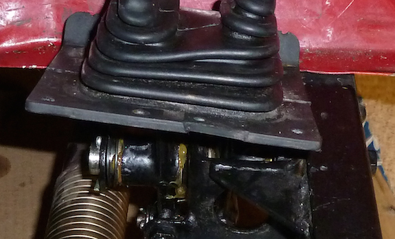
Warning: Do not forget to fit the fume excluder over the pedals before fitting into the car.
While care is needed not to “over ream” the chassis or bushes, the whole assembly can be easily manufactured using a metal lathe.
The 250mm x 18 mm stainless round bar and 1”OD x 1⁄2” ID hollow Bronze tube were bought from www.metals4u.co.uk The 21/32” – 23/32” adjustable hand reamer for the bushes and chassis box and 23/32” – 25/32” adjustable hand reamer from www.totoolsupplies.co.uk The reamers were reasonably cheap and their quality adequate.
I now have two free moving pedals that no longer wobble and are much easier to grease.
Paul Ireland
April 2014
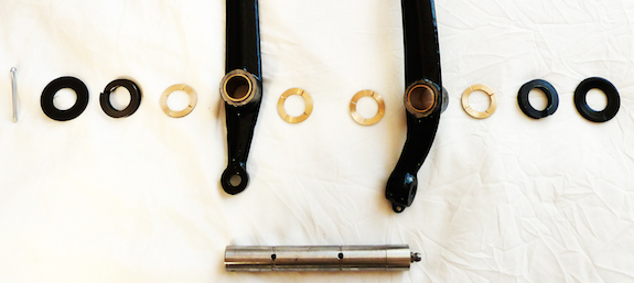
Ed’s note: Drawings of the old and new layouts follow along with photographs of the parts used, the shaft, the location of the grease nipple and the completed job.

Perfectly timed article and inspiration as I am just rebuilding / assembling the pedal arrangement during TC0894’s total restoration.
Amazing idea. I’m just a beginner to the vintage car scene and my TC (0980) has very “Wobbly Pedals”. I’ve dismantled the whole brake/clutch assembly and have asked a precision engineer to make a shaft as described. Thank you very much for sharing your design, very generous. I hope this will cure the problem for many many years. Just a quick question regarding the outer hole… what size hole is this and whats the best way to ensure that it lines up with the other holes for the shaft?
Paul Ireland has sent me the following reply, which he hopes will help:
“If you have wobbly pedals, there are three possible causes (or most probably all):
1) The holes In the chassis are worn
2) The bushes on the pedals are worn
3) The existing shaft is worn
The holes in the chassis are the most difficult to address. The best way (and it is important with the revised design) is to produce an oversized shaft then reamer out the holes in the chassis to match the shaft. This means you will need to assess the size of the holes in the chassis before you get the shaft manufactured. You want the minimum oversize. (e.g. 10 thou over the size of the hole). The taper on the outside of the shaft is to be an interference fit with the chassis to stop it turning in the chassis.
It is possible the bushes in the pedal have not worn as much as the chassis. In this case the oversized shaft then may be OK for the bushes in the pedal, just ream them out to fit the shaft (easier before you reassemble everything). If the pedal bushes are still loose on the new shaft, you will need to replace them as well.
As for the holes. The long axial hole was 1/8” (this was the size of my long drill).. Providing the cross drillings go through the centre of the shaft they will meet the axial hole. Again these were 1/8”. In practice the size of these holes does not matter as long as they are big enough for the grease to go through and not too large to weaken the shaft.
The outer hole is drilled axially to the tap size of your grease nipple. Again size does not matter.”
Excellent idea. My TA1271 will receive this modification, although being in America I will use inch sized stock parts.
Regarding the rivet, my guess is that they trusted rivets more than bolts for chassis work, but couldn’t get the rivet hammer in there to put rivets in the other 3 places, so they used bolts.