I am indebted to Gustaf Ruberg in Sweden for allowing
me to use one of his wonderful drawings for the front cover. Gustaf’s drawing
was in landscape (wider accross than down), whereas we needed portrait (wider
down than accross) for the front cover, so some adjustment needed to be made.
This was entirely beyond me, but that’s what we have sons and daughters for!
Stewart
Penfound, TA/B/C Registrar for the T Register, kindly sent me an account of two
continental tours – in a J2
in the summer of 1949, and, in 1951 in a TA. It was an extract from a
newsletter of a Yorkshire car club and is a fascinating insight into what our
cars are capable of. Even more so if one considers the state of the roads in
Europe just after the end of World War 2.
The 1934 J2 took our intrepid travellers
to Monte Carlo and back, covering 2,000 miles in 10 days.
The J2 was sold after a couple of years’
and a 1938 TA purchased to do a fifteen-day tour of France (which took in the
1951 Le Mans where a British victory – the C-type Jaguar – was celebrated), Switzerland
and Italy. A total of 3,200 miles was covered, with petrol consumption of 33
mpg and oil usage of 2 pints. Considering that this included some “pretty rapid
dashes” which are referred to in the text, such performance is creditable.
The first tour would have been
undertaken before the introduction of roll on/roll off car ferries which were
introduced in Dover in 1951 and as the second tour mentions a “dash to
Boulogne”, loading would also have been done by crane as port of entry to the
UK would have been Folkestone.
In thanking Stewart for thinking of me, it brought back memories of my first journey to mainland Europe. Not that I can remember much about it because I was not much older than seven, so it would have probably been 1953 or 1954.
We …..my brother, who
would have been six and my sister who would have been four, travelled in the
sidecar of what I think was a BSA 350cc motor bike. What I can remember was
that my sister sat on my lap in the front seat of the sidecar and my brother in
the back. Even clearer in my memory was the sound of my mother, riding pillion,
knocking on the roof of the sidecar to stop us arguing (almost certainly
because my brother would have wanted to change seats from the back to the
front).
A subsequent journey several years later in a 1953 Hillman Minx was altogether much more comfortable, albeit it broke down in Belgium with a clogged radiator.
The “height of luxury”, a few years later, was in a 1961 Series IIIA Sunbeam Rapier. By then I was old enough to drive and enjoyed doing 90 mph in top overdrive.
Later in this issue there
is an advertisement for Factory-Original MG T-Series the
successor to Anders Ditlev Clausager’s Original MG T-Series. The
Publisher is offering TTT 2 readers signed copies at a special price. Signed
copies are only available from the Publisher.
I shall be selling copies at the Stoneleigh MG spares day on February 9th
for 27.50 GBP (list price 40 GBP). As usual, I’ll be sharing a stall with Brian
Rainbow (TA Brian) and we’ll be in the same place as we’ve been for the
last umpteen years (Hall 1, opposite Barry Walker).
I should have copies in early November for this price plus postage.
The pic below (and the
details) was sent to me back in the summer by John Elwood in the US. The
Greenwich (CT) Concours featured a special class of Arnolt cars during a two-day
show, June 1st and 2nd. In addition to a pair of
Arnolt Aston Martins, and ten Arnolt Bristols, were six of the 67 Arnolt MG TD
Coupes built and one of the 30 convertibles. This was surely the largest
collection of Arnolt cars in one place since the Arnolt warehouse fire in 1954
burned a dozen Bristols.
A good question and the short answer is…. there
isn’t currently one! But fear not, here’s an article on the various Green
shades you may find useful in helping you find a shade for you. (Colour
examples are included in this article).
My quest started 40 years ago whilst building the mighty Airfix 1:12 Bentley 4 ½ litre kit, the Green colour was quoted as Mid Brunswick Green, surely should this be British Racing Green, I wondered?
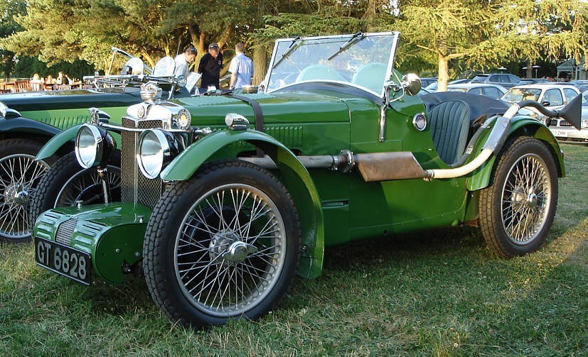
MG Q Type replica 1934 in ‘Brooklands Green’.
Recently I was preparing a project built on a Y type bare chassis and decided to go for a green paint. The project car was to be styled on an MG Q type and the plan is to do the whole car in one shade of Green. This led to me considering a number of green shades.
Not only that, but paint base types; I wanted
to brush the chassis paint and spray the body panels which might present
problems with some paint types. Although the car above looks a mid-green, it is
in sunlight and looks darker in neutral light.
MG over the years has a confusing range of
paint shades, with the same colour having different names across many years. ‘Racing
Green‘ is the factory’s MG TA colour, also known as Dublin Green, EmGee
Green or Apple Green.
Racing Green looks quite acceptable as a
‘British Racing Green’ colour if you want a standard MG shade without having to
have something mixed to pattern.
Paint Ranges
You might come across colours with RAL or
BS4800 codes. RAL is a German system devised in the 1930’s and
the RAL codes are derived from the numerical Red, Green and Blue (RGB) values
of the final colour code – RAL6010 for example is a Grass Green.
Essentially this ‘standard’ means any paint
mixer should be able to produce a tin of paint exactly to the colour made up of
the Red, Green and Blue composition information of the RAL code.
RAL was produced for transport signage
originally, but has grown to many hundreds of colour shades, some with
descriptive names as well as the code number. RAL6010 Grass Green for
example, is often used in restoring lawnmowers and is near to Atco Green.
The BS4800 British Standard shades range
was originally produced for transport related non-vehicle applications but now
covers many vehicle colours too.
UN Paint
codes on containers – a quick guide – This is most important to know!
A tin of paint may have a UN code on it, such
as UN1263, the UN code is a unified coding system for transporters, so that
they know what is in a can before it is loaded for shipment. This is
particularly useful in case of a fire or spillage, so that it is known how to
deal with it and any potential dangers. However, it is not always
straightforward with paints.
UN1263 – is
usually a brushable paint, often called ‘Transport Enamel’, Semi-Synthetic
paint, Synthetic Cellulose, or Alkyd Resin paint. It can be thinned for
spraying.
When purchasing, always buy the recognised
‘pack’ of primer, thinner and top coat wherever possible from the same source,
so that you lessen the possibility of paint reaction or failure during use. Not
all UN1263 code paint products work with each other!
Some brands of UN1263 paint such as Kramp or
Vapormatic are quite heat resistant and are used on Tractor engines as well as
vehicle parts which do not get so hot. Kramp has around 800 colours in their
range. You can buy these on-line.
Brushed or sprayed 1263 semi paint takes around
8 hours to dry off.
Cellulose can be applied over UN1263 if sprayed
in light build up coats, but as always do a test piece first to see that there
is no reaction. Cellulose confusingly has a UN1263 code too! Generally, they are
best kept as separate paints for separate applications. If you do have a lot of
spraying experience then you’ll probably be ok in this case.
Proper Cellulose dries off very quickly, it is
often touch dry in 10 minutes, it does take time to fully harden, a week or
more.
UN1950 – This
covers Acrylic paints and 2k paints which are Acrylic. UN1950 is available in
aerosols, it is thinner in this instance for spraying, it is also available as
a paint in a tin for mixing for spraying. Cellulose can be applied over Acrylic
primer if done carefully. I have done this on guitar bodies using UN1950 filler
primer from an aerosol and then cellulose top coats. Acrylic over Humbrol
enamel or some Oil based paints reacts!
Modern Acrylics in litre tins for spraying are
usually water-based and flat finish, they need a top clear lacquer coat to give
you the shine, you will need that on a water-based paint.1 part and 2K Acrylic
also needs a lacquer over metallic paints without exception.
2k Acrylic used to be an Isocyanate compound
paint but this is now changing to a less toxic paint recipe. 2k is a paint base
which you mix up with an activator (hardener catalyst) compound. Normally this
paint system is used professionally, but you can buy a clean air fed mask
system so you can use it with the right set up at home. Do not use 2K without
an air fed mask under any circumstances, it can cause organ failure and death.
Paint type advantages and
disadvantages:
UN1263 Brushing semi paint – Dries slowly, takes about 8 hours to dry.
Good ‘enamel’ finish (glossy not ‘hammered’ enamel look!) good protection from
weather, will age over time from dirt, rain etc. flexible to an extent when
dried, so good for chassis parts. Used widely on Tractor restorations for
example.
UN1263 Cellulose – Dries quickly, takes a week or longer to
harden off, dries to a nice deep ‘vintage’ sheen, ages nicely on an older car
or restoration, can be cut back by hand with Farecla G3 rubbing compound if
‘orange peel’ finish occurs during spraying, does find edges of filler (often
when heavy coats applied), liable to ‘sink’ where surface imperfections occur,
not widely available as it is only allowed for vintage vehicle use.
Also, liable to sink or ‘search’ into grain of
wood if a filler or sealing primer is not used over wood. Likely due to the
thinners composition, certainly seems more stringent when you get it on your
skin. Recommended for the vintage look.
UN1950 Acrylic – Smelling of ‘Pears’ thanks to the Acetone in
some Acrylics, available in aerosols pre-mixed or in litre and larger sized
tins which can be thinned out for spraying. Dries fairly quickly, can be prone
to chipping. Aerosols useful for smaller items where mixing up a gun of paint
is costly, many shades off the shelf available in Halfords etc. Useful for MG
TC centre console panel type applications.
Sprayed Acrylic from a hand mixed batch is
tougher than from a 400ml Aerosol; it is likely to be a water- based paint
nowadays so will require a clear lacquer coat for a shine. Tougher when clear coated.
Most modern cars are sprayed in this type of paint.
UN1950 2K Acrylic – Mixed from a paint base with a catalysing
activator liquid compound. 2K paints dry in 20 minutes and goes very hard, very
quickly. The sprayed paint reacts with the air in the spray shop and the
activator in the paint to ‘set’ the paint quickly by chemical reaction.
Will go rock hard if left in a spray gun to dry
out and renders it useless – be warned, wash your spray gun out as soon as you
have finished. 2K can be left liquid in a spray gun for around 30 minutes max.
before it starts to go off.
Highly dangerous to spray if you don’t have an
air fed mask system, often only sold for professional use. Finish is often very
‘glassy’ and looks a bit ‘hard’ when compared to Cellulose. Often used on
‘chocolate box’ car restorations and along with oven heating to help cure the
paint off.
Paint types – Here’s how they define these
paints –
1k or
single pack = A Paint base + Thinners.
2K of twin pack = A Paint
base + Activator + Thinners
Paint
matching advice. You may need to be aware of the following…
Optical matching – A Dulux type colour centre has a device
called a Spectrometer which can analyse the RGB (Red, Blue and Green)
values (composition) of the paint colour when scanned. Armed with these values,
you can go to an automotive paint shop and hopefully get the same shade as
analysed. RAL uses RGB Values.
Paint names – One man’s Almond Green may not be another’s.
– On a TA or TB the Green colour shade names don’t always cross refer to the
correct shade for the car.
Model changes may have a ‘new’ shade of Almond
Green that is noticeably, but only slightly different to the previous model. A
move often done in the industry as part of making ‘changes’ to avoid comments
of this car being just a model name change over the previous car.
A good example of name and shade changes is the
British Leyland ‘Brooklands Green.’ This is a fairly mid to dark green from BL
days and a nice BRG style colour, but be aware that Land Rover also used the
name in recent years and their shade is much darker, almost a black / green. So
be aware that old or historical names can be misinterpreted, superseded and sometimes
just incorrect.
This happened to me with this colour! The Land
Rover darker shade was supplied, not the old BL shade. Paint suppliers only
supply what is asked they don’t question, so ensure that if there is any chance
of ambiguity, it is clear what you are ordering!
Original paint – Some caveats to be aware of here – firstly,
some vehicle producers bought paint from the cheapest supplier on the day, or
bought job lots that were either ‘close to’ or ‘adjusted’ in their own paint
shop to the correct colours of their products. Different pigment origins can
also affect the end colour too.
Secondly, paints can fade with UV light
exposure. Green isn’t too bad in this respect, but Blue and Red shades really
do oxidise and ‘weather’ badly. (Often a good rub with T-Cut does get back to a
good example of the original colour by cutting down to sounder paint layers
below).
If you can find a part like the inside of a
glove box lid, that’s likely to be the closest you’ll get to an ‘original’
shade, as it has likely had less UV exposure to fade it.
However… be aware that the paint on the top
of the car may have been refinished to a close shade at some stage after and
the inside parts weren’t, so do some detective work to ascertain if you can see
evidence of a refinish that may differ from the shade you are looking to
achieve.
Also, a previous owner may say ‘they painted it
in ‘xxx Green’ when the shop may have just used a paint they had near to that,
so again, do your research because it’s too late when it’s on the car!
Colour chip cards with the original paint
colour on are available from some paint suppliers.
Computer monitors can give various different ‘versions’ of what
a paint shade actually is from monitor to monitor, according to how they are
either calibrated, or handle the colour or how the video card displays colours.
The golden rule really, here is to ideally have
the colour in your hand. It’s too late once you open the tin, or start
spraying! (or order it and find it is way off the shade).
Thorough mixing – Some paints may have been on the shelf for
up to a year or more and the pigments and solids have settled, really stir the
paint up well to avoid thin paint without proper ‘body’ which can affect the
end colour.
Test paint colour on a sample piece before you
go anywhere near your car with it, see the paint dry and decide if this is the
correct shade.
How will your car look in
this shade? Sometimes a colour might
look good on the chip card but on the car, it doesn’t quite look right. Have a
range of colours to try.
Two tone colour schemes – Lay colour chip cards over each other so
that you can see how both shades work together – or don’t. The paint sprayer
often only will spray what you specify. Once they start spraying, they are
usually committed! So, avoid undue expense by not getting it wrong at this late
stage!
RGB to RALconversion– You can visit a site with a
conversion process where you put in the RGB colour values and can in many
cases, get a direct or close RAL code equivalent.
Some paint shops don’t use the RAL system. So,
take an actual paint sample they can match to, or take a Spectrometer reading
from.
PRE-1960
paints safety – Many
if not all Pre-1960 paints contain Lead, take care when removing old Pre-1960
paint, it sticks and lasts a long time to things because of the Lead!
Ok, let’s go Green…
Here we’ll look at some Greens in the range to
give you an idea. These are ‘on-screen’ colours so do ensure you have an actual
paint sample to compare for the final decision before you buy. Always look at a
spread of colours before making your final choice!
Shades of Green – Blue and Green makes Yellow as we all know,
but in our consideration of dark green colours the Blue or Yellow tone can
affect the ‘warmth’ of the colour.
Shades like Atlantic Green, used on a 1947 YA I
owned had a lot of ‘blue’ tonation, much like a Norwegian christmas tree type
of shade, what I would call a ‘cold green’ look.
A ‘Castrol’ type Green has more yellow in and so is a ‘warmer green.’ I prefer warmer green shades personally.
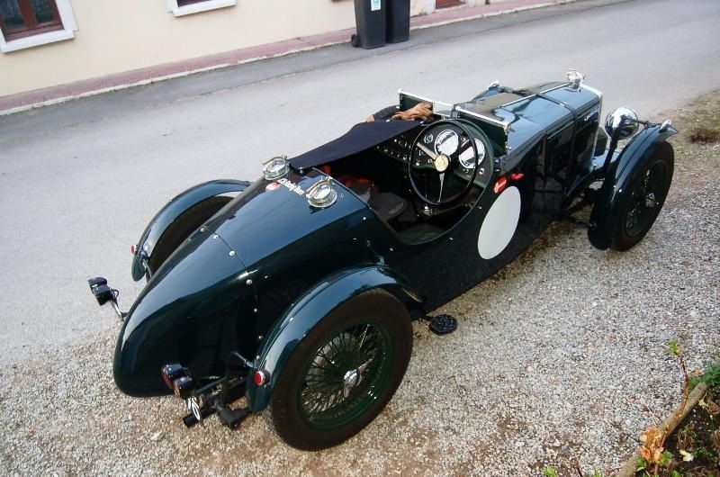
EXAMPLES OF COLOURS ON CARS
MG C type in a Light Brunswick style shade
MG PA in light Brunswick
MG PA Special in Mid Brunswick Green
MG TA/Q in a very Dark Green with ‘Blueness’
MG TA/Q in a Green with blue hint similar to YA Atlantic Green
Above left: MG TA in a Racing Green shade right: MG
TD in a darker Green perhaps Woodland?
MG TA Tickford in Westminster Green and an Opaline style shade
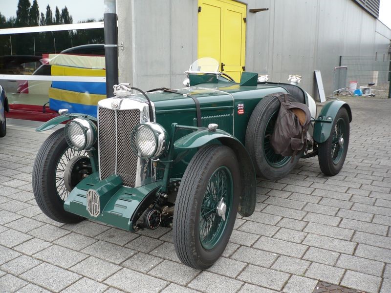
MG Q Type replica in Brooklands Green
I hope that you have found this article useful, if any members have enquiries regarding paint for restorations then contact me by email on fender57red(at)yahoo.co.uk [Please substitute @ for (at)] or call 01544 350320.
Ed’s
note: Thank you Matt Sanders for a most informative article.
I hope it will be particularly helpful to those who have reached the painting
stage on their restoration, or those who are contemplating a respray.
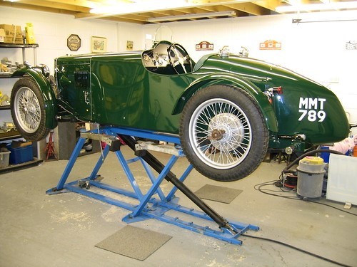
Geoff Fletcher has been sending me photos of his rebuild as it
progresses and I thought I would share some of them with readers; they might be
particularly helpful to those currently engaged on rebuilds.
Geoff is no stranger to rebuilds, albeit not with MGs. His Healey pictured below, which he has owned for 40 years, has been restored/rebuilt by him twice now, the second time needing a chassis replacement.
The car was a chance barn
find and the owner, a local farmer, took some persuading to part with it. Geoff
told me that admirers of the Healey sometimes think he is
rich owning such a car, but he originally paid £350 for it. At the time of
purchase, a marque expert’s advice was to scrap the car and to let him find one
in better condition for Geoff. This offer was politely declined.
Geoff first e-mailed me back in October 2017. He had read my
article on bushing front leaf springs using SAE 660 bronze and had contacted
Brost Forge to make a pair of main leafs (leaves) with oversize 5/8 inch
‘eyes’.
Ed’s note: Sadly,Brost Forge ceased trading in June 2019. I always found the proprietor, Chris Wann, to be most helpful and his springs were extremely good. Yet another old established supplier, who has decided to call it a day.
Chassis TC8365 obviously needing a good clean
and paint. (October 2017)
That’s much better! (October 2017)
Above: Cylinder block before work started Below: looking better (October 2017)
Condition of the gearbox (October 2017)
By March 2018,thegearbox had
been stripped and cleaned, components, gears etc rebuilt onto shafts with new
bearings. Synchro’s were very good showing little, if any, sign of wear. Everything
was stripped and cleaned, including synchro hubs. The whole lot was covered in
what looked like varnish, but it was the old oil that had dried and had coated
everything inside and out. Degreaser wouldn’t move it, and it was necessary to
use a solvent based degreaser/cleaner.
Also, by March 2018 work had commenced on building up the chassis, with the front and rear springs fitted and the front axle in position.
Shackle plate arrangement at the rear of the rear spring and front of rear spring is fitted with a silentbloc bush suspended on a ½” diameter ‘pin’.
Shackle plate arrangement at the rear of the front spring and front of front spring is suspended on a ½” diameter ‘pin’. Front axle is in situ.
By August 2018 Geoff had rebuilt the gearbox with great attention to detail as the next picture shows and all but rebuilt the engine. As part of the engine rebuild, he cleaned the head studs with a die nut, but got so far down and it started to cut into the threads. A good way of finding out that your studs have stretched. New studs were purchased.
March 2019 – backplates, kingpins, hubs, shock absorbers, hydraulics, fitted.
March 2019 – more work on the engine and radiator now fitted. Wiring started.
Geoff bought the extractor manifold when he first purchased the car and was told by the dealer who sold it to him that it was a direct replacement. However, it was nowhere near as it fouled the steering box and would have needed to be modified, which Geoff was reluctant to get involved with. He therefore decided to revert to the standard arrangement, as shown in the next picture.
By April 2019 Geoff had changed the exhaust manifold back to standard and fitted the carbs and a heatshield (next picture).
Geoff sent me an update towards the end of July. At the time, he was just finishing making and fitting the brake pipes “not my favourite job, getting the bends right etc” he said. He’d also ordered one of Tom Lange’s stainless steel thermostat housings and is very pleased with it: https://mgtrepair.net/Thermostat.html
At the time his differential was with Roger Furneaux for rebuilding and fitting with a higher axle ratio; he now has this back from Roger. He’s also received a 20 thou oversize sector shaft from Andy King and bought some new Blockley tyres. Having sent the wheels away for truing and finishing, he is hoping to soon have a rolling chassis and will send more pictures then. To close, here’s a couple showing work on the brake pipes.
Available from early November is this new book, the successor to Anders Ditlev Clausager’s Original MG T-Series, which was first published in 1989 and was constantly in demand and in print for 30 years until 2018, when work on the new book got underway.
Whilst Original T-Series contained 104 pages and 150 colour pictures, the revised and enlarged Factory-Original MG T-Series runs to 160 pages with more than 340 illustrations.
The aim remains the same, namely to provide a detailed guide, in words and pictures, to correct factory specification and equipment of all models of the MG T-Series cars from TA to TF1500, including the TA Tickford drophead coupe.
The publishers,
Herridge & Sons Ltd, are offering TTT 2 readers a discount of 7.50 GBP off
the normal price of 40 GBP for signed copies, post free to UK addresses.
Post to Europe is 5 GBP and rest of World 12 GBP. The discounted price of the
book, inclusive of postage is therefore 32.50 (UK) 37.50 (EU) and 44.50 GBP
(Rest of World).
Readers should use the discount code MGTTT19 and you can order via the publisher’s website: www.herridgeandsons.com or phone 01409 281990, or by post to Herridge & Sons Limited Lower Forda, Shebbear, Beaworthy, Devon EX21 5SY.
Please note: Signed copies are only available from the Publisher.
I have two copies of Mike Sherrell’s TCs FOREVER -MORE! These are priced at 60 GBP plus UK postage of 4 GBP.
Payment for TCs
FOREVER – MORE! Can be accepted
by bank transfer to:
Account Number 3345 8268 Sort Code 77-73-11 or cheque payable to The MG ‘T’ Society Ltd and sent to John James at: 85 Bath Road, Keynsham, BRISTOL BS31 1SR
By David Braun P.E. Email: [email protected] Website: http://www.dbraun99.com/
The following is a simple step-by-step guide for tuning your SU carburettors using a different method from that usually suggested in the various books published by BMC, Haynes, SU or Burlen Fuel Systems. This paper doesn’t try to explain how to rebuild your carburettors, the manuals available on the market do a fairly good job of that. Instead, it allows you to perform some simple tests to determine the condition of your carburetors as they sit on your car; how to adjust them; or if you need to remove them and repair certain functions.
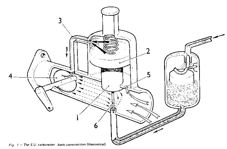
Fig. 1 The S.U. carburettor – basic construction theoretical From Tuning S.U carburettors by G. R. Wade
Piston venturi. Squeezes down the area of flow.
Piston surface. This is a clearance fit that governs the drop test times. If the piston is brass (or has steel weight on upper rim) no spring is needed.
Suction dome vent. Communicates the downstream pressure with the upper side of the piston.
Throttle disk. Controls the amount of air the engine receives.
Piston vent. Communicates the upstream ambient pressure with the lower side of the piston
Needle. Moves up and down with piston to increase or decrease the amount of fuel picked up from the bridge.
The
SU carburettor has four moving parts. Taken in order of their function, they
are:
The
float and needle;
The
sliding jet to facilitate starting;
The
throttle disk and shaft;
The
variable venturi piston and suction chamber.
Assuring that these four parts are in
working order and then adjusting these parts to work in concert with each other
(and in multiple carburettor set-ups, with the other carburettor(s)) is the key
to tuning the SU carburettor.
Preparation
Setting up and tuning an SU carburettor
is based on the premise that both the engine and the carburettor are in good
shape. The following should be checked on the engine prior to setting up the
carburettor to determine if the situation will lend itself to optimal timing,
or if expectations should be lowered to ‘good enough’.
XPAG or XPEG Engine
‘B Series’ Engine
Engine Compression
This will assure even airflow through the intake manifolds into the engine.
About 145 psi all cylinders within about 15
psi of each other
About 170 psi all cylinders
within about 17 psi of each other
Valve clearance Helps the engine breath by
facilitating airflow at the proper moments during its cycle.
Follow the indication on the valve cover or
as suggested by the manufacturer of the cam installed, but likely 0.019,
0.015 or 0.012 inch for an XPAG; 0.015 or 0.012 inch for an XPEG
As suggested by the
manufacturer of the cam installed, but likely 0.015 inch.
Sparkplug Gap Promotes the complete
burning of the combustion charge under compression.
0.025 inch with standard coil and points.
0.030 inch with Pertonix ignition.
0.032 inch
Dwell sets up the cycle period of the coilwith
standard points (omit with electronic ignition –Pertronix but do check the
wires for chaffing inside the distributor cap).
0.015 inches of point gap will yield 60º of
dwell with the high lift distributor cam.
0.015 inches of point gap
will yield 60º of dwell with the modern distributor cam.
Timing Initial setting to time the
flame front in the cylinder. Use whatever timing advance your car will
tolerate without pinging under load.
A good starting point is 8º before top dead
center (BTDC) static timing or at low idle. With 8º static and 25º mechanical
advance the timing will be about 33º at 3,500 rpm.
14º BTDC at idle with the
distributor advance vacuum hose disconnected and plugged.
In
addition, the carburettor should be checked carefully for: (already
completed on rebuilt carburettors)
The throttle disks should seat evenly in their bores with no sticking or misalignment, with the sharp edge seating last.
The pistons should pass the suction chamber drop tests at the same rate: 3-5 seconds for a 1-1/4″ and smaller carburettor 5-7 seconds for a 1-1/2″ and 1-3/4″ carburettor.
The throttle shafts should be secure in their bores with no noticeable leakage.
The jets should be centered and the needles should not show evidence of wear from sliding along the sides of the jet.
Correct
any questionable conditions in either the engine or the carburettors. The
tuning methods will still be helpful but optimal results will only be achieved
on a well-maintained engine and carburettor system.
Theory
The
manuals, including the SU publications, state that the float bowl fuel height
is set by inserting the properly sized bar stock or a drill rod between the
forks of the shut off lever and the lid. (already completed on rebuilt
carburettors) Since the float bowl fuel height is directly communicated to
the bridge fuel height (a liquid seeks its own level) it is important to get
this measurement correct. The manuals rarely tell you that the resulting level
of fuel at the bridge should be 0.120 to 0.200 inch below the bridge.
The other critical item to be undertaken
is the depth of the jet below the bridge. (already completed on rebuilt
carburettors) The manuals give the starting point as six flats (one full
jet adjusting nut turn) down. But what they don’t tell you is that the
preferable starting point for the depth of the jet below the bridge is 0.070
inches. Again, there are several factors that can affect the relationship
between six flats and the optimum
depth of the jet and the corresponding depth of the carburettor needle.
Thickness
of the jet adjusting nut
Length
of the jet
Packing
around the jet centering nut
Carburettor
body thickness
Placement of needle in the piston.
On a single
carburettor installation, the variances are not a big deal, but on
multi-carburettor installations the manuals suggest that each adjustment is
made the same amount on each carburettor. If the variances stack against each
other so that the starting points of the two essential measurements are not the
same on each carburettor, making each adjustment the same amount on each
carburettor will not result in the same state of tune for each unit. Varying
the settings on either carburettor independently of the other will soon result
in confusion and a lack of certainty with respect to both the starting point
and the state of tune achieved. The following method will eliminate much of the
confusion, provide an excellent starting point for tuning and allow for
consistent results. Consistent results will yield the maximum performance of
the fuel delivery system to the engine, which in turn gives us the maximum
performance that can be reasonably expected. And that’s exactly what we want.
In Practice
These instructions
are for existing carburettors and provide several good starting points. For
rebuilt carburettors by dbraun99 LLC, the steps already completed are noted. In
general, note that the pistons and suction chambers are paired, and should not
be mixed and matched without reason. Any parts that are removed should be replaced
in the same orientation on the same carburettor from which they were removed.
Placing items on a clean cart in order of removal is advised. Some of the parts
are old and of dissimilar metals. Corrosion may be present. Proceed cautiously
with disassembly to avoid breakage.
Step
1. (already completed on rebuilt carburettors) With the air cleaners removed, unscrew
the caps and remove dampener and rods from the top of the suction chambers.
Check that the jets are centered by lifting the pistons to the top of their
travel and allowing them to drop. They should fall quickly to the bridge with a
satisfying click. If they hang up midway or don’t fall fully to the bridge,
center the jets.
Step 2.(already completed on rebuilt
carburettors) Remove the suction chambers and pistons from the carburettors,
being careful not to mix up the two sets, and being careful to assure that the
pistons and suction
chambers remain in exactly the same orientation to each other. Pour out the
dampener oil. Note that the venting holes in the pistons go to the rear of the
carburettor body and are keyed by a side or front key.
Step
3.(already
completed on rebuilt carburettors) If you haven’t completed your drop
tests, plug the vent holes (and the top of the suction chamber, if you have the
vented type) and perform the tests, allowing the suction chambers to drop off
the pistons onto a soft surface.
Step
4.(already
completed on rebuilt carburettors) Using a dial caliper or metal rule,
adjust each needle to the same depth from its corresponding piston face.
Step
5.(already
completed on rebuilt carburettors) Remove the choke return springs from the
choke assemblies at the bottom of the jets and screw the jet adjusting nuts to
their full up positions. Exercise the jets up and down in their packing.
Step
6.(already
completed on rebuilt carburettors) Turn on the ignition and let the pump
click until the bowls are full, or turn the engine over and allow the
mechanical fuel pump to fill the bowls. Now look down from the top of the
carburettor and note the height of the fuel in the bridge. Move the jet up or
down until the level of the fuel stabilizes in the bridge and the height of the
jet matches the level of the fuel. It will take several tries to get this
right. Using a dial calliper, measure the depth of the jet below the bridge.
Since the jet is now residing at the same height as the fuel, the depth of the
jet represents the depth of the fuel below the bridge. Each carburettor should
have the same fuel depth within ± 0.020 of each other, and both fuel depths
should be 0.160 ± 0.040. It takes some practice to measure the depth of the jet
below the bridge. The goal is to keep the dial calliper perpendicular to the
bridge. The dial calliper, if set too tightly, will push the jet down, disrupting
the measurement, and if set too loosely will make it difficult to accurately
measure the depth.
Step 7.(already completed on rebuilt
carburettors) The difference in the measurements from optimum in each
carburettor bridge is the amount the fork must be changed in the corresponding
float bowl lids. Either eyeball the change and re-check, or measure the current
setting of the float fork with bar stock or a drill rod and select a new bar or
rod of the correct size. Each 1/32 difference in rod will change the setting
0.03 inch. Do not be surprised if the new settings are vastly different from
the original 7/16 inch quoted in the manuals (for H Series) or 3/16 inch (for
HS Series), and different for each float bowl.
Step
8.(already
completed on rebuilt carburettors) Remove any excess fuel if needed, refit
the float bowl lids and allow the pump to refill the bowls. Repeat the
measurement in Step 6, and repeat Step 7 if needed. Reinstall the float bowl
lids a final time once you are satisfied.
Step
9.(already
completed on rebuilt carburettors) Lower the jet adjusting nut 9 flats down
(1-1/2 turns of the nut). Set the dial calliper at 0.070 inch and lock the
setting with the setscrew. Reposition the dial calliper as you did for the fuel
depth measurement and turn the jet adjusting nuts up a flat and push up on the
jets to fully seat them against the nuts. Repeat until the jet is 0.070 below
the bridge. It may be necessary to back off the adjustment a bit the closer it
gets to the proper setting. Continue to keep the jet fully against the
adjusting nut. This is the starting point for idle mixture on the carburettor,
and probably within 0.010 of optimal.
Step
10.(already
completed on rebuilt carburettors) Replace both piston and suction chamber
assemblies being careful of their orientation. Recheck the piston drop to
assure that the jet is still centered. If the jets are not centered, adjust as
needed and repeat Step 9.
Step
11. Loosen the throttle
bar clamps and make sure each throttle moves independently from the other. Back
off the idle adjustment screws, then turn each down one full turn.
Step
12. Start the engine.
After a bit of warm up adjust the throttle screws EVENLY until a steady 1200
rpm is achieved. Using a Unisyn, a rubber hose, or SU kit cat’s whiskers adjust
the idle screws INDIVIDUALLY until the rush of air into each carburettor is
equal, and the car is idling at 1200 rpm when warm.
Step
13. Lock the throttle
bar clamps. Note that locking the clamps does not preclude some twist and
variance caused by the accordion form of the clamps, so it is important from
here on that both idle adjustment screws be adjusted the same amount.
Step 14. With the engine turning over at 1200
rpm, raise each jet adjusting nut one flat and note if the engine increases or decreases.
Go up a second flat on each jet. At each adjustment assure that the jet is
fully against the jet adjusting nut. When the idle speed starts to decrease,
note the number of flats. If the process has taken more than a minute, clear
the engine by blipping the throttle.
Step 15. Note the engine rpm. Readjust the
engine to 1200 rpm with the idle adjustment screws. Turn the adjusting nuts
down (lowering the jet) one flat at a time on each unit. Note the number of
flats for the greatest increase in engine rpm and also where the rpm starts to
decrease as you continue to lower the jet adjusting nuts. The difference
between the greatest engine rpm and where it starts to decrease should be about
two flats. Adjust the jet adjusting nuts to be between the greatest engine rpm
and where it starts to decrease.
Step 16. Clear the throttle and adjust the
engine rpm with the idle adjustment screws to between 500 and 800 rpm depending
on your preference. With the flat of a screw driver just beneath the piston,
rotate the blade to lift the piston 1/32 of an inch and listen to the exhaust
note. It should speed up momentarily and then settle back to idle. If it speeds
up and stays there, raise each jet adjusting nuts up one flat. If the engine
speed falls off without increasing, lower the jet adjusting nuts down one flat.
If no change is perceived, leave the jet adjusting nuts where they are.
Step 17. With the engine off, top off the
dashpot oil (engine oil is fine) to within a half-inch of the top of dashpot
chamber. As long as you feel resistance when you install the damper and rod you
have enough oil. You need a vented cap on the dashpot if you have a non-vented
dashpot chamber. You need a dustless cap (one with no vent) if you have a
vented dashpot chamber. Reinstall the air cleaners.
Step 18. Take the car for a test drive. It
should be set to go. There are additional fine-tuning techniques which can be
employed during a test drive to both optimize needle selection and to assure
optimum fuel air ratios. On a close to standard engine with standard carburettors,
these tests should not be necessary. If acceleration and response aren’t
satisfactory, and your engine passed the tests noted above, you may need to do
further fine-tuning or search for another problem.
Safety Fast!
A note about the author and dbraun99 LLC:
Dave Braun is a registered
mechanical engineer who practices in the areas of aircraft propulsion, systems
and certification. He works closely with his clients to assure that designs and
manufacturing processes meet FAA requirements and result in safe, profitable
and durable products for OEM and aftermarket installations. He is delegated by
the FAA to make design approvals on their behalf.
Dave
restored his MG TD from 2005 to 2008, developing a website with photos and text
to aid in his eventual reassembly of the car. The website grew and was
discovered by enthusiasts so he made it available to thegeneral public. There is a donation link on the
bottom of the front page of http://www.dbraun99.com/ to help fund the cost of hosting the site. Since then,
Dave has restored a 1970 MGB and those pictures are on the site as well.
In the
process of tuning his newly restored TD, Dave discovered that a lot of the
practices advocated were flawed and/or based on the best technology available
at the time of the manufacture of the car. He set out to develop procedures and
processes that would allow a more precise tuning given the changes in the
intervening years. This carburettor manual is one of those procedures. dbraun99
LLC is also available to rebuild carburettors for various British cars.
Dave has been published on his
own website, and in various club newsletters and magazines, including many
articles in MG Driver, the magazine of the North American MGB Register.
He serves as technical coordinator for the North American MGB Register.
2011-2017 by David Braun, P.E.
Ed’s note
FAA
= Federal Aviation Administration, an operating mode of the U.S. Department of
Transportation.
OEM = An original equipment manufacturer
(OEM) is a company that produces parts and equipment that may be marketed by
another manufacturer. The largest OEM company in the world by both scale and
revenue is Foxconn, a Taiwanese electronics company which manufactures parts
and equipment for companies including Apple, Dell, Google, Huawei and Nintendo.
“Thanks very much for an interesting article but I’m having trouble understanding the explanation. I don’t see that reversing the polarity changes the path the electrons take nor the resistance they encounter. Doesn’t it just make them flow in the reverse direction?
I came across this: https://mgaguru.com/mgtech/ignition/ig104.htm which confirms that polarity is important but for a different reason. That is that the central electrode of the sparking plug needs to be negative since electrons prefer to jump from hot to cold.”
Graeme Hogg posted the following
comment:
“I too have been confused as to correct coil polarity and when researching the subject came up with two articles that appear to disagree with Steve and John’s conclusions as to the correct way around to connect the coil. Both also suggest that spark plug polarity is the more important factor.
Moss Motors at Coil Polarity and MGA Guru at https://mgaguru.com/mgtech/ignition/ig104.htm make for interesting reading. Perhaps Steve might check his spark plug polarity as described in the two articles and observe whether his current coil connection gives the “correct” plug polarity as defined in the articles.”
Peter Cole and Eric Worpe also contacted
me and they have kindly produced the following article, starting from first
principles.
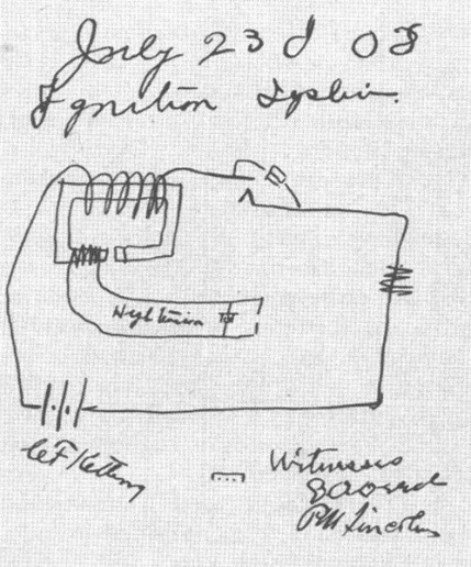
The ignition system used in our cars was invented by Charles Kettering in 1908. Fig 1 shows part of his original patent submission. His ignition system was used in nearly every car made worldwide exactly as he described it from soon after its invention until the mid-1980s. The Kettering ignition is an extremely simple and reliable arrangement consisting of an ignition coil, a condenser (see Note 1 at the end of this article) and a contact breaker, more commonly referred to as ‘the points’. Prior to that time cars used a magneto to produce the ignition voltage. Whilst the magneto was significantly more expensive to manufacture, it had the advantage that it could produce a spark without a battery. More recently, refinements were made to Kettering’s ignition system such as adding a transistor to extend the life of the points or adding a resistor in series with the coil primary, which could be shorted out to aid starting. Essentially however, even with a few tweaks, these ignition systems are directly attributable to Kettering.
Fig 1
The ignition coil consists
of two windings, the low voltage primary and the high voltage secondary
winding. The ratio between the primary turns
and secondary turns was typically between 1:50 on early coils and up to 1:150
on modern coils. The coil produces the
spark voltage by transforming the 400-500 volts across the condenser and the
open points up to the 10 – 20kV required to produce a spark at the plug.
Our cars were originally
wired with the positive terminal of the battery connected to the chassis, which
is termed ‘Positive Earth’ or ‘Positive Ground’ in the States. The coil terminal marked ‘SW’ is connected to the negative 12V battery supply via the
ignition SWitch and the terminal
marked ‘CB’ is connected to the Contact Breaker which, in turn, connects the CB terminal to earth when the
points are closed. The primary and
secondary windings are connected together inside the coil and are designed to
produce a negative spark voltage (see Note 2 at the end of this article). A negative spark voltage is desirable because
the spark plug gap will break down at a lower negative voltage than it will
with a positive voltage. This makes use
of the ‘thermionic’ effect whereby the hotter central electrode of the spark
plug will emit electrons more freely than the cooler spark plug body. Hence a negative spark voltage will provide a
stronger spark. However, some cars such
as the Citroen 2CV use a coil where both ends of the secondary are
accessible. Here, one end of the
secondary is connected to one plug and the other end is connected to the other
plug. The benefit, at least in terms of
cost, is that there is no need for a distributor, but one plug has a negative
spark voltage and the other a positive spark voltage. So, whilst a negative spark voltage is desirable
it is clearly not essential.
So, this raises several questions: Does a T-Type with positive earth, using an
original Lucas Q12 coil, produce a negative spark (see Fig 3)? What happens if the battery polarity is
reversed? Does a modern car, with
negative earth produce a negative spark (see Fig 4)? What happens if a modern coil with terminals
labelled + & – is used to replace an original coil with terminals marked SW
& CB in a positive earth T-Type (see Fig 5)? Will it still produce a negative spark? What
happens if the coil connections are then swapped (see Fig 6)?
Any
of these possibilities may be encountered in a T-Type today and possibly more
than one. Swapping the polarity of the
battery is commonly done to accommodate modern electronics such as a Sat Nav or
LED light bulbs. Swapping to a modern
coil is becoming increasing likely as original Lucas coils, some of which may
be more than 75 years old now, reach the end of their useful life.
To answer these questions, it is necessary to look at the ignition circuit in more detail and to consider some of the coil, coil connection and battery polarity permutations most likely to be encountered. In doing so it might be helpful to refer to Fig 2 which shows the internal construction of a typical ignition coil and how the primary and secondary windings are arranged. Fig 2 is reproduced by kind permission of Robert Bosch GmbH and is taken from their publication Ignition Systems for Gasoline Engines. (ISBN 3-934584-63-2)
Fig 2 Construction of a Typical Ignition Coil
Key to Fig 2:
1 High voltage output 2 Inter-layer paper insulation 3 Coil terminal insulator 4 Interconnection between secondary start and high voltage output 5 Case 6 Wide strap to fix coil to the car and aid cooling 7 Outer magnetic core 8 Primary winding 9 Secondary winding 10 Filling, usually asphalt 11 Base insulator 12 Inner magnetic core
1) T-Type with Positive Earth, using the original Lucas Q12 Coil wired as intended.
Fig 3 (Note: in Figs 3-6 ‘S’ and ‘F’ refer to the start and finish of the coil windings).
Referring to Fig 3, the finish of the primary winding SW is permanently connected to the negative 12 volt battery supply via the ignition switch. At the start of the ignition cycle the points close connecting the start of the primary winding CB to earth. Current starts to rise in the primary towards a level determined by the winding inductance, the winding resistance and the duration of the dwell period. As the engine speed increases the magnitude of the primary current at the end of the shorter dwell period will be lower, and hence there is less energy stored in the coil to produce a spark.
At the end of the dwell period the
points are opened by the cam on the distributor drive shaft. The primary current then charges the
capacitor across the points. The primary
inductance forms a tuned circuit with the capacitor to produce a voltage across
the points of around 400-500 volts. This
is transformed by the coil to provide the voltage to necessary to create a
spark at the plug. The spark voltage
will be in the range 10 – 20kV depending on conditions inside the
cylinder. The spark voltage will be NEGATIVE and the voltage at the points
augments the secondary voltage.
Note
that if the connections to the SW and CB terminals of a Q12 coil or the battery
polarity are swapped the spark voltage will be POSITIVE. Swapping the SW and CB connections of the Q12
coil after the car has been converted to negative earth would revert to a
negative spark but don’t do it! Note the
warning in the conclusion later in this article (after the commentary on Fig 6)
2) Modern car with Negative Earth, using a modern coil.
Fig 4
Referring
to Fig 4, the primary start (labelled +) is connected to the positive 12 volt
battery supply via the ignition switch.
At the start of the ignition cycle the primary finish (labelled -) is
connected to ground via the points. As
the points open the secondary spark voltage is NEGATIVE but the
primary voltage does not augment the secondary voltage.
3) T-Type with Positive Earth, using a modern coil.
Fig 5
Referring to Fig 5, the primary finish (labelled -) is connected to the negative 12 volt battery supply via the ignition switch. At the start of the ignition cycle the primary start (labelled +) is connected to ground via the points. As the points open the secondary spark voltage is NEGATIVE and primary voltage augments the secondary voltage.
4) T-Type with Positive Earth, using a modern coil, with the connections swapped.
Fig 6
Referring to Fig 6, the primary start
(labelled +) is connected to the negative 12 volt battery supply via the
ignition switch. At the start of the
ignition cycle the primary finish (labelled -) is connected to ground via the
points. As the points open the secondary
spark voltage is POSITIVE but the primary voltage does not augment
the secondary voltage.
So in conclusion, we can see that no
matter which type of coil you use, no matter how it is connected and no matter
how your battery is wired you will end up with a spark that will run your
car. Some combinations produce a less
effective positive spark voltage, so are not ideal. This may be evident during starting when the
battery voltage can sag to 7 or 8 volts, so starting may be difficult or even impossible. It may also be evident at higher engine
speeds when the energy stored in the coil is less so the engine may start to
mis-fire. However, none of the
combinations of coil type, battery wiring, and coil connection will result in a
situation that will overheat the coil, nor stop the car running, at least in
the short term, but there are two possible areas of concern.
The first is when the connections to an
original Lucas Q12 coil are reversed.
Under these conditions the SW terminal is exposed to the voltage across
the points (up to 500 volts) rather than the intended 12 volts battery
voltage. This may cause the insulation
inside the coil between primary start and the outer magnetic core to fail.
The
second is when a modern coil intended to be used with a ballast resistor is
used without one, or with one of too low a resistance. This will overheat the coil causing it to
fail and quickly burn out the points.
The way to avoid this is to check the coil primary resistance (between +
and – terminals) of the coil using a digital ohmmeter. The original Lucas Q12
coil has a primary resistance of 4.2 ohms and the period accessory Lucas
‘Sports’ coil has a primary resistance of 3 ohms. This primary resistance defines the ultimate
primary current whilst the points are closed, at least at low engine
speeds. As long as a modern replacement
coil has a primary resistance in this range it can be used as a direct
replacement for an original coil. A
modern coil intended for use with a ballast resistor may have a primary
resistance of less than 1 ohm, so must be used with a series ballast
resistor. The value of this should be
chosen so that the total ballast resistor + coil primary resistance is around 3
to 4 ohms and must be rated at 50 watts.
Notes:
Note 1.The purpose of the condenser,
which today is more correctly termed ‘capacitor’, is to slow the rate of rise
of the voltage across the opening points.
Without it the barely open points would arc and the energy stored in the
coil’s magnetic core would be dissipated before a spark voltage is produced at
the plug. Many capacitors sold today for
classic cars are notoriously unreliable.
Anything with ‘Lucas’ printed on it is either at least 50 years old now,
or more likely a poor quality Far Eastern copy.
Eric has recognised this and can offer a reliable modern capacitor
encased in a copper sleeve ready soldered onto a base plate ready to fit into
your distributor. These are offered on
an exchange basis. A description of the
problems he has found with early capacitors, and some modern replacements too,
was published in TTT 2 Issue 31 (August 2015).
A copy of the article can be downloaded from the TTT 2 website by
selecting the relevant issue from the dropdown box. The article is well worth reading as it gives
a fuller description of the operation of the T-Type ignition system.
2.The
polarity of the spark voltage can be checked by using back to back LEDs in
series with one of the spark plug leads as described by David Heath and
others. By using separate red and green
LEDs or a single bi-polar red/green LED in series with the plug lead the spark
voltage polarity can readily be detected.
Examples follow:
Fig 7A shows a LED spark polarity tester using a bi-polar Red/Green LED which fits onto one of the spark plugs in series with the ignition lead. Fig 7B shows the tester in use with a Lucas Q12 coil, wired as intended in a positive earth car. This demonstrates the car has a negative spark voltage as indicated by the green LED. Fig 7C shows the same car, but with the connections to the SW & CB coil terminals temporarily reversed resulting in a positive spark voltage as indicated by the red LED.
Wrapped (bi-metal) kingpin bushes for TB/TC and later TA
Bi-metal ‘wrapped’ king pin bushes – note the oil/grease groove which has a spur take off that feeds lubrication to the thrust faces of the beam axle’s eye.
Bi-metal ‘wrapped’ king pin bush showing the spur groove that feeds the thrust washer.
Eric Worpe now has these bushes in stock. He needed to advance a not
inconsiderable sum of money to be able to offer these bushes at a price which
is significantly lower than the phosphor bronze type available commercially.
The important point to note is
that the wrapped bushes are the correct type (as used originally when the cars
were new) and by ordering in bulk it is possible to pass on significant
savings.
Details of price and availability below:
For a set of 4 the cost is 32 GBP. For orders of between 3 sets of 4 and 9 sets of 4 the cost is 30 GBP per set of 4. For orders of 10 sets and above the bushes can be purchased for 28 GBP per set of 4.
Postage
at cost on all orders.
These
bushes will be available from the Editor at his stall (shared with Brian
Rainbow) in Stoneleigh in February.
Enquiries to e.worpe(at)btinternet.com [please substitute@ for (at)]
Wire
wheels refurbishment
Geoff Fletcher, whose restoration
progress is featured elsewhere in this issue has e-mailed to say that he has
just picked up his wheels from The Wheel Specialist, Garforth/Leeds
after being blasted, powder coated and tyres (Blockleys) fitted. He says that they
have made an excellent job and can recommend this company to anybody wanting
some wheels refurbished in this area. They also fit tyres so they do the
everything, which has its advantages.
Dave’s Doughnuts
Since
the last issue I have ordered another 20 pairs and now have these in stock,
albeit two pairs of these have just been sent to France to be fitted to an MGA
and an NA. The last pair of the previous batch was sent to Neil Cowking, who
reported back as follows:
“Goods received, fitted, tested, clonk
gone!”
To order a pair, please send an e-mail to the editor at jj(at)ttypes.org [please substitute @ for (at)].
TA/B/C
Brakes – Fitting of Thackeray washer
Paul
Busby has been in touch as follows:
“I have recently had the good fortune to work on two TCs
previously maintained and serviced by others. Whilst overhauling the brakes on
both cars I was concerned to notice both had the Thackeray washer (double
spring washer) the wrong side of the brake shoes. This was most evident on one
car by the wear pattern in the lining. The Thackeray washer should be behind
the two shoes not in front, with the wide horseshoe retaining clip bearing
direct onto the shoe.”
Paul goes on to say that the manuals do not show sufficient detail on this but simple dimensional checking will make it clear. He is amazed how people even manage to fit the horseshoe over the Thackeray washer. This incorrect fitting also allows the washer to become unwound through the gap as most people also do not recognise the horseshoe should be used once and crimped closed just like a split pin.
Above: Thackeray washer in place before crimping. Below: This pic is without Thackeray washer as Paul could not hold together and photograph with one hand. Pin is new and up a few thou to take up wear.
Pic from the linings from one of the two TCs Paul worked on, showing wear patterns due to mis-alignment.
Paul Ireland’s new book
Paul’s
new book is currently being printed and should be available for Stoneleigh in
February, where it can be purchased from the Editor’s stand.
“Just to let you
know I am still at it” was
the opening line of a recent e-mail from Michael Sherrell. Mike had recently
returned from the Coalfields 500 Race Meeting held on 20/21 October at the
Collie Motorplex, just over 200 kms and two and a half hours south of Perth.
Just before the event weekend, he was advised that he was the only
entrant in his class. Whilst he would have preferred to have been competing
with a host of TCs and like machines, he was happy to be
at the back of a field of open wheelers, Caterhams etc. just to learn and enjoy
the new track layout. The track has been
extended on from the main straight through a series of interesting bends, to a
sharp left, on uphill though a combination of lefts on the top, then steeply
down left and right, the last being a tricky little squiggle, on to the
existing back straight – chicane, left and left, and back on to the main
straight once more.
Mike
summed up his weekend driving experience as follows:
“I drove my
supercharged TC to Collie via the excellent Mornington Rd, competed in five,
ten-minute events over two days, then drove home unscathed, again via
Mornington Rd, on a high, energised and elated and so proud of my little
TC/9349. What a machine!”
Ed’s note: I would add…..What a competitor!
Two pics of TC/9349 at the Collie Motorplex.
Restoration Services
Some months‘ ago I was contacted by Mike Gardiner from Pangbourne with
the request; Did I know of a reliable company who would finish his J2 and
get it back on the road? I had no hesitation in recommending Adrian Moore
of Finishing Touch Bodyshop in Weston-Super-Mare.
The work that needed doing on the car was mainly mechanical and Adrian
picked the car up from Mike’s home and delivered it back when the job was
finished.
I was pleased to receive this picture from Mike with the comment “Adrian did just what I asked for – get the car in a state that I could drive it – he’s a nice chap to deal with – and every time you go, there is something else that is interesting to see! ”
That’s what I like, a job well done at an affordable price and a satisfied owner! (Ed).
Head
Gasket and Bottom End Sets
I
have a head gasket set for TB/TC/TD (to engine no.22734) and Y (to engine no.
17993). Good quality set made by Gaskets For Classics Limited. Price is 40 GBP
plus postage.
I also have 3 head gasket sets for TD 22735 on, YB and TF to chassis no. 8173 i.e. TF1250. Price as above. jj(at)ttypes.org – substitute @ for (at)
Also
for sale are several bottom end sets for TB to TF priced at 18 GBP plus
postage.
When
they are gone they are gone!
Tracing
the current owner of a once owned MG
I was surprised to read in the November issue of Enjoying MG that
the DVLA recently helped an individual to trace his grandad’s TC. The individual
submitted a DVLA form to the Agency along with some old photographs and a
reason why he was trying to trace the car. Nothing happened for a while, until
one day there was a telephone call from the present owner.
I say
I was surprised, because I tried this unsuccessfully some time ago (I even
followed it up via my Member of
Parliament). At the time, I felt that there were unconvincing reasons advanced
for the refusal, chief of which was that such a request did not meet the reasonable
cause criteria.
I
shall now contact Matthew Whiteman, who is trying to get in contact with the
present owner of his late father’s TC and we will see what DVLA have to say.
Ross
Harris in Australia has been in touch. I was sorry to hear that his dad
(Claude) whose TA, (TA1980) was featured on the front cover of the October 2011
issue, died recently. Claude was 92.
Ross has just acquired TA2982 to keep TA1980 company. Originally registered in the UK as ETC 334 it was owned at one time by a T-racer, who purchased the car around 1960 in Swindon.
TA2982 was brought to Australia by a lady called Ann Pridham in the late 1980s, and up to now had been in the possession of Phil Dadd from Sydney for the past 30 years.
Ross
would be interested to learn of any history of the car pre-1960 – jake(at)mgta.com.au [please substitute @ for (at)].
He
is also seeking Photos and information on the Factory MG TA Trials cars
originally registered BBL 82, BBL 83, BBL
84 and BJB 412. (Musketeers) and or contact with the owners of Cream
Crackers BBL 78 BBL79 BBL 80 and BBL 81.
Ross
is familiar with M.G. Trials Cars by Roger Thomas, having read it
several times from cover to cover, but he is seeking more detail of the cars.
TC0918 (JUM 427) Paul Richmond is trying to locate the whereabouts of his late father’s TC. He owned it from 1947 until 1953, when he had to sell it – the impending birth of Paul’s older brother meant a more family friendly car was required! The car was originally green, but was restored and painted red in the nineties and last heard of in Sheffield in 2013. Contact Paul on 077 3148 0291 – pfrguitar(at)gmail.com [substitute @ for (at)].
This website uses cookies to improve your experience. We'll assume you're ok with this, but you can opt-out if you wish. Cookie settingsACCEPT
Privacy & Cookies Policy
Privacy Overview
This website uses cookies to improve your experience while you navigate through the website. Out of these cookies, the cookies that are categorized as necessary are stored on your browser as they are essential for the working of basic functionalities of the website. We also use third-party cookies that help us analyze and understand how you use this website. These cookies will be stored in your browser only with your consent. You also have the option to opt-out of these cookies. But opting out of some of these cookies may have an effect on your browsing experience.
Necessary cookies are absolutely essential for the website to function properly. This category only includes cookies that ensures basic functionalities and security features of the website. These cookies do not store any personal information.
Any cookies that may not be particularly necessary for the website to function and is used specifically to collect user personal data via analytics, ads, other embedded contents are termed as non-necessary cookies. It is mandatory to procure user consent prior to running these cookies on your website.