We
had a marvellous weekend in mid-Wales on the Totally T-Type 2 tour
and couldn’t have wished for better weather. Since we’ve now been
back for a couple of weeks‘ it is noticeable how autumn has
arrived, almost without warning – chilly mornings and evenings and
the days seem to be progressively getting shorter.
One regret was that I didn’t get the opportunity (it being the Bank Holiday weekend) to visit the Riversimple company, who are based in Llandrindod Wells where we were staying. This young company https://riversimple.com is using hydrogen fuel cell technology in a car, known as the Rasa, which has been designed with aerodynamics in mind and a lightweight body.
I
find nowadays that unless I write things down I completely forget.
Having spoken to Colin Fitzgerald, owner of TA0251 following the
publication of an article on the two prototype TAs, TA0251 and TA0252
in Issue 54, I promised him that I would clarify in Issue 55 some
comments made about his car. Of course, I completely forgot!
The debate was about the differences between TA0251 and TA0252 and in commenting on TA0251’s body style I said that it is not known if this rear body styling was original to the car, but it seems odd that two cars built as prototypes within one month of each other would have such different styling at the rear.
Colin was concerned that my wording could
have been interpreted as casting doubt on the originality of the body
styling of his car and pointed out that this was how the car was
before he bought it and that a number of experts had inspected the
car. This was not my intention and I am happy to publish Colin’s
remarks to set the record straight.
We
have had a number of visitors to 85 Bath Road, Keynsham in the last
few weeks.
John
and Robin Libbert from Milford, Ohio were visiting the UK, which
included, inter alia, a trip to Pre-War Prescott. As one of their
overnight stopping places was Bath, just down the road from us, they
called in for a ‘natter’.
Last weekend we had a visit from Douglas and Yani Wallace from Jimbaran, Bali, Indonesia. They were accompanied by Doug’s pal, Derek Simpson from Norwich and Ian Wilson from Brough, East Yorkshire. Ian is the Chairman of the MGCC MGA Register. They were on their way to west Wales where they were overnighting before catching the ferry to Ireland.
A couple of days before penning this editorial Carl Drolshagen from Sorup, Schleswig-Holstein, Germany called in. Carl had been to the Beaulieu autojumble and was on his way to the Midlands to visit an old friend. Carl has two Triple-M cars and a TC.
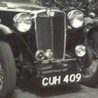
I didn’t have room for the above picture in Lost & Found. It is TC0281, formerly an Oxford police car.. Filiep Vandamme is trying to trace the car’s history. filiepvandamme(at)gmail.com [please substitute @ for (at)]
The scammers have been at it again. Oleg Shekhovtsov and James Atwood have both been active. Mr Atwood has been replying to WANTED adverts for virtually every model of the T-Series and he also says that he has an MG (model not given) which he wants to sell for the giveaway price of $3,800 due to his health issues.
The
accounts for The MG ‘T’ Society Limited for the year ended 31st
October 2018 are included in the website under PUBLICATIONS. Go to
www.ttypes.org
click on PUBLICATIONS and input your user name and password.
I bought my MG PB in September 1998, so it’s been a ‘love affair’ for nearly 21 years.
The picture opposite was taken by my son, Stephen just before setting off from our hotel for Goodwood Revival 4 years ago.
Following purchase, I was disappointed to learn that there was no documented history of the car for the period between 1936 and 1945, and subsequent enquiries of the DVLA ran into the sand.
The sales advice which was completed at Abingdon for every finished car, records, on signing out from the Despatch Department, that chassis number PB0722 was delivered on 26th March 1936 to the Main Agent, University Motors.
The sales advice recorded such details as vehicle type, chassis, engine, gearbox, rear axle and body numbers and even dynamo and starter numbers. Also recorded were body, upholstery and wheel colours.
My car was original in all respects, apart from the rear axle number and I put that down to transposition of numbers – well that’s my story and I’m sticking to it!
Although the car was built on 27th January 1936 (Source: Production Records) and delivered to the Main Agent by the end of March, it was not sold until 23rd May. The selling garage was Chesterfield Motors of London NW 1, who would have been supplied with the car via the Main Agent.
The first owner was a Mr Cyril Wentworth Hogg of Clarendon Mansions, Brighton. Even if Mr Hogg purchased the car at the tender age of twenty, he would be a centenarian now; possible, but unlikely.
As first owner of the car, Mr Cyril Wentworth Hogg’s name appears on the returned Guarantee card.
A Guarantee card was sent with each new car to the supplying dealer, who was responsible for handing it to the purchaser. He or she (yes, some ladies bought these cars!) then needed to sign the card and return it to Abingdon for the guarantee to become operative. Not all cards were returned.
It is not known how long Mr Hogg kept the car, for as mentioned previously, there is no documentation between 1936 and 1945. However, it is possible that he owned the car immediately prior to it passing on to (what might have been) the next owner, Mr L J Cato of Taunton. There is a letter in PB0722’s file to Mr Cato, from Mr Haddock of Abingdon’s Service Department dated 14th August 1945. This letter gave a diagnosis, in response to the symptoms described by Mr Cato, of wear on the shoulder of the nearside front hub, and suggested the fitting of shims between the inner bearing race and the hub. However, it was regretted that Abingdon could not supply the necessary shims!
I saw the car advertised in the MG Octagon Car Club ‘Bulletin’ (of which I was then editor) for £18,500. At the time, money from a redundancy settlement was ‘burning a hole in my pocket’ and I simply had to buy the car. I paid the full asking price, which on reflection was a tad too much – but the amount overpaid, amortised over a period of twenty-one years is of little consequence (or so I tell myself!).
The previous owner had restored the car and had a pile of bills in support. He had bought the car from Geoffrey Jennings (now deceased). There is an entry in Geoffrey’s name, dated 1959 in the continuation log book (the original is missing) and it looks as though he sold the car in 1968.
Geoffrey’s brother Phil, is the co-author of Oxford to Abingdon, that wonderful tome that catalogues the early days of MG.
I’m not sure whether Geoffrey managed to completely restore the car – he certainly seems more than a little fed up with it in this action shot!
From the look of the following picture taken around 1956 at either Boreham or Fairlop aerodrome, Essex, the car appears to be in reasonable condition. However, appearances can deceive as I discovered when I removed thebody tub from my J2 which before its body was taken off, looked to be a very nice ‘up together’ car: it literally fell apart, a victim of woodworm.
However, PB0722’s original body was found on close examination to be sound with new timbers having been skilfully let in under the running boards.
Soon after I bought the car, I took it for MoT – it failed! The most serious failure point was kingpins and I had these renewed and also fitted new front springs.
I decided to have the engine rebuilt in 2006/7. This was a wise (but expensive!) move because, when the engine was stripped down, I was advised that the white metal conrod bearings were starting to break up.
My engine builder, Brian Taylor of Hopton Heath in Shropshire, was none too keen to use a 70+ year old crankshaft in the rebuild, so I had one specially made with uprated conrods. Shell bearings were used for the conrods and the centre main was adapted to take shell bearings, with the rear main retaining the white metal.
During the lengthy period of the engine rebuild I became aware of the possibility of fitting an overdrive to the car. I bought an early MGB unit from a retired Laycock engineer in Sheffield and took it with the PB gearbox to Barrie Dean in Nottingham. Barrie weaved his magic and I was pleased with the result.
The early MGB overdrive mated to the PB gearbox prior to installation in the car.
The overdrive installed in the car. A shortened propshaft was required and it was a relief to find that the unit just cleared the fly-off handbrake (by about an inch).
The fitting of the overdrive (frowned on by some owners of the overhead camshaft MGs) is easily the best modification I have done. It helps to make the car so much more relaxing to drive on a long journey…and we’ve done quite a few over the years, including motoring in France.
Ed’s note: Overdrive is fitted to some other 4-cylinder MGs, including my J2, and also to some 6-cylinder models.
The last journey in PB0722 was on the annual T-Type weekend that I organise every August. We had a wonderful few days in The Cotswolds in the company of 37 other MGs – mainly T-Types, but also a couple of RV8s.
The next picture was taken on arrival home from The Cotswolds. Under the black polythene is a large box containing two new TA/TB/TC/Triple-M roof racks.
The last pic comes as I wipe away a tear – you’ve been a wonderful little car, but all good times must come to an end – farewell old friend, please keep in touch!
PB0722 being loaded into Steve Baker’s van for its journey to Lincolnshire and thereafter to Italy.
Postscript: As I conclude this article the car now has FIA papers and it has been exported to Italy, where it is eligible for the Mille Miglia – only two pre-war “standard” – exotica apart – MG models are eligible for this iconic motoring event; the L2 and the PB. Of the T-types, only the TB is eligible.
Ed’s note: Readers maywonder what happened to the T-Type records.
Most of the Triple-M records (in the form of a chassis file for each car) have survived, thanks to the vigilance of Mike Allison, who saved them from destruction. Unfortunately, the T chassis files, numbering over 50,000 (5 times as many as the Triple-M) were unable to be saved, as the time window for saving them was relatively short, and all were destroyed, probably around the late 1960s/early 1970s.
The ‘Build Books’ which list chassis number, engine number and date of build (in effect, the Production Record) have, fortunately, survived and are held in the offices of the MG Car Club in Kimber House, Abingdon.
Having browsed the Internet and watched various YouTube videos about Altette horn repair, it seemed to me that they are regarded with some trepidation. (YouTube video 1951 Vincent Rapide, Part 38).
This is worth watching as it describes visually what I am trying to say in this Altette guide.
I
therefore hope that this description of my efforts may help some
other enthusiast to pluck up courage and delve into the Altette horn.
I
had the beaten up remains of a late Altette Horn HF1234 12 volt horn
that I planned to use on my PB, however I understand that this type
was fitted to very late TA/TB/TCs – not sure about this detail, but
seems possible, so I thought that ‘Totally T-Type 2’ might be
interested in my attempts to get this horn working.
Ed’s
note: The
HF1234 wascertainly
fitted to the TC. The 1937 TA was fitted with HF934/2.
This
type of Altette has a cast iron body and is a simplified version of
the earlier horns of the same name, shape and style.
After dismantling the horn,
I found that the points were not connected correctly i.e. leads
broken and the insulated Tufnol terminal plate was cracked, and there
was a flat cupped washer with a rubber insert rolling around on the
inside of the casting without any apparent use?
The
shims were non-existent.
The
chrome bezel on my horn was extremely rusty and corroded, so I
purchased a new bezel, new fixing bolts, Tufnol terminal plate and a
set of shims from ‘Taff The Horn’. After reading through Taff’s
website and the paperwork he sent to me with the parts, I realised
that what I thought was going to be an easy job might be more
difficult.
I
decided to retain the rusty bezel and after de-rusting and
resurfacing the pitted steel, I painted it chrome colour, just in
case that it might be useful in the future (more of which later).
This
has all the technical information that you are likely to need when
fixing these horns.
After
de-rusting the cast iron body and un-seizing the fixing and adjusting
screws on the rear of the body, I was ready to start rebuilding and
here begins some of the conundrums. The Lucas Workshop Instructions
did not “exactly” identify my particular model, therefore it is
important to get to understand the principles of operation and then
apply the knowledge to your particular horn.
On
this particular Altette there are just 3 screws on the back, 2 small
screws are side by side and they secure the points assembly to the
base of the cast iron body, and 1 larger screw that “levels” the
points (it does not “adjust” the points gap).
Picture
1 showing rear of Altette and the location of the screws referred to
in the text.
The
first check I carried out was to establish if the coil was any good
by checking its resistance.
Connect
your ohmmeter across the terminals and take a reading; according to
the Lucas Workshop Instructions, our 12 volt version should read
between 0.70 and 0.75 ohms. Assuming all is well, turn your attention
to the inside of the horn casing.
The large screw on the reverse controls the “level” of the points, not the adjustment of the points gap; by turning the screw in or out you will see the points assembly tilting left or right, the object is to get them level within the body of the horn. At this point I realised what the cupped washer with the rubber insert was for. It fits on top of the adjusting screw and provides a cushion to prevent the screw damaging the electrical connection (I think that’s correct, otherwise I’m stumped!).
Picture 2 showing the
cupped washer with the rubber insert.
Next job is to clean the points, these are clamped together with their appropriate flat springs. However, you will notice that there is a triangular Tufnol area with 2 tiny brass rivets attached and when this “ear” is pressed down with your finger, the points will be forced open and it’s possible to insert a strip of emery/wet and dry to clean the points.
Do not force the points open with a lever, just use finger pressure. If you break the points it’s game over and you will need new points – if you can find them!
Now it’s time to think of the shims! I did not have a clue as to “how many” I would need, so I opted for 3 thin ones (Taff supplied various thicknesses). Start with say 2 thin ones on the horn body, then fit the diaphragm. If you dismantled your Altette and shims were fitted, start your rebuild using them as they are a good starting point. Make sure you impregnate shims with Vaseline, don’t use gasket cement of any kind.
Bearing in mind how flimsy the shims are, it’s a good idea to use two 3/16 BSF studs screwed into the horn mounting holes on each side of the horn and fit the shims over them, this helps locate the shims and later the diaphragm.
Pic 3 – 3/16 BSF studs
help locate the shims.
Having fitted the shims fit the armature, this has an aperture on two sides and it’s an easy matter to sit it into the larger magnet core face. Fit the diaphragm, making sum that the diaphragm is the correct way around; my opinion is that the convex side faces outwards i.e. the bulge around the rim of the diaphragm faces outwards (see next pic).
Diaphragm fitted – convex side facing outwards
Screw on the large lock nut, ensuring that diaphragm sits on the shallow ledge machined into the armature and fit the fixing bolts around the diaphragm and tighten them and then tighten the large lock nut.
Fit the points pushrod and its locknut into the armature and screw the pushrod in until you feel it “bottom” – do not over tighten. Hopefully you are now ready to make your first attempt to achieve a sound from your Altette.
Make sure that you use a 12v battery for testing and not a battery charger. I used a cheap 12-volt burglar alarm battery, being convenient and lightweight – at my age I find car batteries a bit too heavy for me.
Rig
the 12-volt battery with a lead to one of the 2 terminals on your
horn. Using the second lead from the battery gently touch the second
terminal on the horn, if you do not get a sound do
not hold the lead in contact –
‘Taff the Horn’ warns of this, over and over again – as you are
likely to melt the points. At this stage they are probably closed
i.e. no gap therefore “no sound.”
This is the point at which your patience is demanded, gently turn the screw half a turn and then touch the lead to the horn terminal. If no sound, try another turn and so on, always making sure that you do not touch the terminal for too long.
Assuming the you do not get a sound from the horn, dismantle the whole assembly, then fit an additional shim under the diaphragm and repeat the whole process!
Hopefully,
after carrying out this exercise a couple of times i.e. adding shims,
suddenly you get a strangled sound from your horn. Perhaps rather
weak but nevertheless “a sound”. Now it’s a question of
gently screwing the points push rod in or out until a reasonable
sound is achieved, not forgetting to adjust the locknut up tight, as
the points rod will quickly unscrew when the horn works. This
surprised me as the operation of diaphragm is quite violent and
unless the locknut is tightened you may lose it.
The
points adjuster and locknut have a very fine thread and not easy to
reproduce or find.
So, at last “It’s Alive” and now it’s a further exercise in patience. Find your bezel and make sure that it is still “round” and that there is no old paint or rusty bumps on the inside of the rim.
Also, find the orientation that the bezel was fitted; originally the Lucas logo was at the top, however some bezels have lost their surface finish and who knows where the logo was?
I found that my original bezel had been assembled for so long that it had taken its shape from the casting i.e. it fitted beautifully when using the fixing bolts that hold the horn to the bracket, however turning it one sixth and it did not fit!
Once again ‘Taff the Horn’ insists that the fit is close but not binding – remember that the diaphragm should be held firmly and softly by the shims and not clamped by the bezel in any way.
Once you have sorted your bezel it’s time to fit shims i.e. remove all of the perimeter fixing screws and place your chosen number of shims on top of the diaphragm (I ended with 3), fit the bezel and perimeter screws and tighten them carefully.
Go back to your battery rig and touch power to the terminal as before, do not be surprised if you get no response! Revert to the points adjuster and carefully go through the adjusting sequence again, you should soon get your sound back, it might sound puny and weak; it’s up to you to adjust until you get the sound that you think adequate.
Do not expect the mellow tone of the Twin Windtone with its High and Low horns, the sound from the Altette is harsh but insistent.
Assuming that all is well, fit the Tone Disc and the large dome cover nut, making sure that points locking nut is “locked”. Then try the horn again, it may sound fine — but then again it may not, so remove the Tone Disc and play with the adjuster until you can achieve a sound that suits you.
You can see from all of the above that every time that you tighten or fit components the points adjuster is affected i.e. the points have been opened or closed. The correct air gap between the Armature and the Magnet core face is 18 to 20 thou on our 12 volt Altette, but because it’s under the diaphragm it cannot be seen.
The Lucas Workshop instructions explains, how to measure the gap using a dial gauge. I did not want to spend even more time setting up a “rig” with a dial gauge to establish the gap and then find that I had to alter it to get a sound.
‘Taff
the Horn’ suggests using an old bezel to avoid damaging your new
chromed bezel whilst carrying out adjustments. Bearing in mind the
number of times that the perimeter screws are fitted and then removed
to fit shims etc that’s not a bad idea. By now, you should have a
horn that works!!
I hope that this long explanation of my experiences with the Altette will help someone else to attempt to repair their rusty horn.
Please note that I am not an auto electrician or an expert in any way and also, I have no connection with ‘Taff the Horn’ other than being a satisfied client of his and appreciating his efforts to educate me in the operation of Altettes.
Since publication of Eric Worpe’s article in the previous issue of TTT 2 there have been a couple of comments as follows:
Peter Bick had a similar problem with a Jaguar with oval eyes and was told that braking causes the kingpin to rock forwards and backwards, inflicting more wear in the axle eye. When the cars were in production, Jaguar listed a .008” oversize kingpin, but now of course, these are generally unavailable.
However, he managed to find a NOS (new old stock) pair of kingpins, which he had hard chromed and then ground 0.10 inches oversize to fit the reamed axle eyes to suit.
While hard chroming the kingpin he also had a hole drilled and tapped at the top of it to take a 5/8 inch blot. A swaged wire strop was attached with an adjustable turnbuckle back to a bracket on the chassis so that now every time the brakes are applied this strop should stop the kingpin from moving forward.
From recent experience, Jeff Townsend confirms all of Eric Worpe’s findings relating to the sale of undersized kingpins in the UK. He says that while Eric was fitting new spindles to the stub axles of TA1957 he asked him if he could fit new kingpins and bushes at the same time. Having purchased a set from one of the trade suppliers, Eric found that the pins were up to 0.5 thou undersized. Further investigation indicated that pins from other suppliers might be the same.
It was indeed fortunate that Eric got to hear that Gerry Brown was having some 2 thou oversize pins made. Whilst the TA axle had been straightened and steering geometry reset as far as possible, the eyes were found to be slightly oversized. The oversized pins are now a good fit in the eyes.
Eric also fitted some original ‘wrapped’ (bi-metal) bushes, so the car is well engineered around the front hub area. In fairness to the undersized pins supplier, a no quibble full refund was offered and accepted.
Ed’s note: Eric is expecting delivery of the wrapped (bi-metal) bushes by the end of September. Price will be very competitive.
Chris Tinker, long time TC owner, uses his car far more than most. The front cover shows his car in front of the Café de Paris, Monte Carlo. Here’s a short account of the car’s history…
I’m back from a wonderful expedition this summer through France and on to the Piedmont area of North West Italy. To drive up to the world-famous Café de Paris, Monte Carlo has been a long-held ambition and MPA 894 was welcomed despite notices barring entry to this idyllic spot. The TC has driven admirably, with only a flat tyre and a snapped fan belt to hold me up. I sent John a photo or two and he kindly agreed to publish them, and asked for a short article on the car and my ownership. Thus a few words….
I bought it as my first car in 1972 for
£450, in a driveable condition. It needed to be, being my sole means of
transport. The first bill, from J J Silencer of Canterbury, was for an MOT in
October that year, at a cost of £1.70 ……… I also have records in the front
cover of my handbook of refuelling, and petrol averaged about 35 pence per
gallon.
In
early ownership I looked after everything despite not being an engineer, as so
many current owners seem to be! According to my mother’s diary of those years,
I spent literally hours under my car keeping her roadworthy. The first matter was a slipping clutch! I had
to remove the gearbox, and the handbook came in useful at that stage as did my
Publican who had a gantry so that I could lift it out. I’d never even seen a
clutch plate before. This was learning on the hoof!!
Further
work on my own included keeping the bodywork in reasonable condition – I had a
marvellous little Humbrol spray for patching up the lovely primrose yellow
colour. This colour led, by the way, to the car’s name, the Noddy Car, as it is
known to the family.
In
the mid-seventies I see I used Octagon Sports Cars (London E17) for parts – as
one example, a front spring cost me about £5.25 in 1974. So far as professional
work was concerned, Toulmin were called in for some work as listed on an
invoice I have – lots of work around the engine including water pump and carbs,
and even a new brake master cylinder. The bill was a massive £122.97 so I must
have been feeling rich!!
Looking
through my log of the 80s, I managed to fit new big end shells and a new rear
spring, performed a de-coke, rebuilt the carbs over one winter (much enjoyed
that!) and so it goes on. A decade later
I remember fitting a new wiring loom.
The
engine was reconditioned in 1979 by Baileys of Canterbury at a cost of £289
including parts, and has been twice since by Richard Coles of Coltec – I had a
high lift cam for a while but it failed, and I decided to go back to standard.
George Edney did his unleaded head conversion back in the ‘90s, and it has
served me well ever since. Since my earlier efforts to maintain the paintwork,
it has been professionally sprayed, 1980 and 1987. And then in 2010 I had a
major rebuild by Tom Pizzey which included a further respray with the modern
two-pack paint which continues to hold up very well. For spares these days I am lucky to have NTG
just down the road – they are friendly and efficient and I am a regular
customer!
I have enjoyed many Continental holidays in the TC, visiting such places as Geneva, Lugano, Florence, Siena, Rome, our Honeymoon in Brittany/Paris – including parking right under the Eiffel Tower – and Christine and I have also driven through the Rioja valley and on to Salamanca and Madrid. Alpine passes conquered include the Simplon, the San Gotthardo, the Grimsel and the massive Stelvio.
Above:At the Barolo vineyards above Alba (Italy) Below: by the coast at Antibes (France).
Of
course, driving a TC is not always going to be without incident. Back in the
earlier days I remember smoke rising from below me – this was not the usual smoke
from some leaking oil, but white smoke!
I looked under, rather perturbed, to find that the blowing silencer had
almost set the wooden floor just above it on fire! This was quickly
extinguished, and I then applied some silver foil to the wood to prevent
further potential fires until I returned home and fixed the exhaust.
On
another occasion, a core plug fell out, leaving me without water. This was
behind the carbs, so off they came by the roadside with emergency services
rolling up to see what was the matter… I knocked in a new core plug, my
co-driver acquired water from a nearby house, and we were off again within the
hour. I do carry plenty of spares!! Lucky to have the core plugs though.
Other
problems have included a piston blown at the top due to running with too weak a
mixture, a blown head gasket (just last year in France!!), a snapped fan belt
and rather more flat tyres than I would like.
I
also had a leaking joint on the oil pump to filter pipe quite recently near
Orleans, and made up my own washer with some old inner tube I always carry. It
is still fine, so I’m leaving it alone! The only really alarming failure was
the steering box drop arm – fortunately at a very slow speed in a Devonshire
village
This summer I topped 150,000 miles, and as I spent three years out of the country, this comes out at about 3,500 a year. I never completely lay the car up as I like to take advantage of those dry sunny winter days (often February) to go out for a run and let the cool dry air blow through the vehicle just in case any condensation has been encroaching. And I usually have a Christmas day drive.
Chris out in Provence within the last 6 weeks.
I
intend to plan further expeditions and would love to join another Autumn Tour
(TTT 2 or T Register) though dates are difficult for me. However, I actually
hosted one once (based near Ipswich) and my wife and I joined a Yorkshire one a
few years back based at my birthplace Skipton. So, onwards and forwards – (not
upwards yet I hope!) – I love driving my
first car and will continue to make much use, sometimes daily again maybe, of
this treasure.
Ed’s note: I think this
is a perfect example of man and car in harmony.
When Chris’ mother was alive and living in Bude,
Cornwall, Chris used to call in on us for lunch and a chat, having set out from
Ipswich in the TC that morning. Suitably fed and watered he then set off for
Bude.
Ipswich to Bristol is just over 200 miles; Bristol
to Bude is around 130 miles.
Having recently changed the SU pump on my TF1500, (the previous owner had asked a garage to fit a new pump and a late MGB pump had been fitted, which was not to my liking) I did some research on the Internet and found the following:
L (low pressure pumps) – These are found on the T-Series (TA, TB, TC, TD and early TF) and earlier MGs.
They develop up to 1.5 psi and have a flow rate of 1.3 pints per minute (9.6 gallons per hour).
HP (high pressure pumps) – These are found on late TF, MGA, Z Magnette and early MGBs.
They are the same outline and size as the low pressure pumps or sometimes come with a longer coil housing (referred to as a High Pressure/Long Body pump).
They develop up to 2.7 psi and have a flow rate of 1.1 pints per minute (8.4 gallons per hour).
LCSpumps – These were used on the MGA Twin Cam and on the Austin Healey.
They use the long coil body of the High Pressure/Long Body pump and have a large, rectangular pump body on them.
They develop up to 3.8psi and have a flow rate of 2 pints per minute (15 gallons per hour).
AUF 300 series pumps – (now AZX 1300 series) – These are found on all of the later MGBs plus many British cars of the 1960s and later.
They have what is called a “plain air bottle” on the inlet side and a flow-smoothing device on the delivery side.
They develop up to 2.7psi (AZX 1307) or 3.8 psi (AZX 1308) and a flow rate of 2.4 pints per minute (18 gallons per hour) for both types.
From
childhood Dinky toy days, it was my desire to own an MG. Although
there were many other makes, the name MG seemed to be the car
synonymous with the term ‘sports car’. In December 1963 at the
end of my first year as a poorly paid apprentice, I managed to have
saved some money and assisted by my mother with a reluctant loan, I
bought my red TD for R320 (then about PDS160). A joyous moment and
that first drive home from in a howling south east gale is today
clearly embedded in my memory.
The
price of the car soon faded but the loan share had to be repaid and
in the coming months there were times when I could not afford petrol,
which was as I recall, about R3.60 (PDS1.8) to fill the tank.
Nevertheless, I was driving my dream and enjoying every moment behind
the wheel or under the bonnet. It was particularly sporty driving
with the windscreen down and too poor for the luxury of aero-screens
which perhaps explains my hairless crown today.
Lunch time on Cape Town’s own Daytona Beach – 1964
Bloubergstrand Cape Town – 1974
At
the time of buying the MG, a sweet 12 year old girl named Frances,
lived across the road from me. Some 5 years later she started taking
a rather keen interest in both the MG and its owner. Thus, began the
‘romantic period’ and the TD, now sprayed racing green became
known as ‘Cosy’ for obvious reasons! On 6th February 1971, 50%
ownership of my TD was
unwittingly
relinquished to the ‘girl across the road’ at our wedding
ceremony. Later that evening our ‘Cosy’ took us for a short
honeymoon to Stellenbosch.
As
time moved on, the TD saw only occasional use due to my marine
career, purchase of our home and a growing family naturally took
precedence. Dear old ‘Cosy’ showed her displeasure at this
neglect and eventually refused to budge from the garage due to major
defects. Sadly, this is where she then reclined for the next 33
years, but thankfully was not sold, as so often happens.
Eventually
restoration began in earnest in 2007/8. After so many idle years
and living near the salty air seaside the car was indeed in a sorry
state. Those who have tackled a complete restoration know the
frustration and disappointment experienced during the course of the
project. However, perseverance pays and the end result is an
incredible sense of job satisfaction, achievement and pride.
Having
owned our now Clipper blue TD for 55 years and after so many years
off the road we are once again, at every opportunity, enjoying the
soothing exhaust burble taking us back to our younger years.
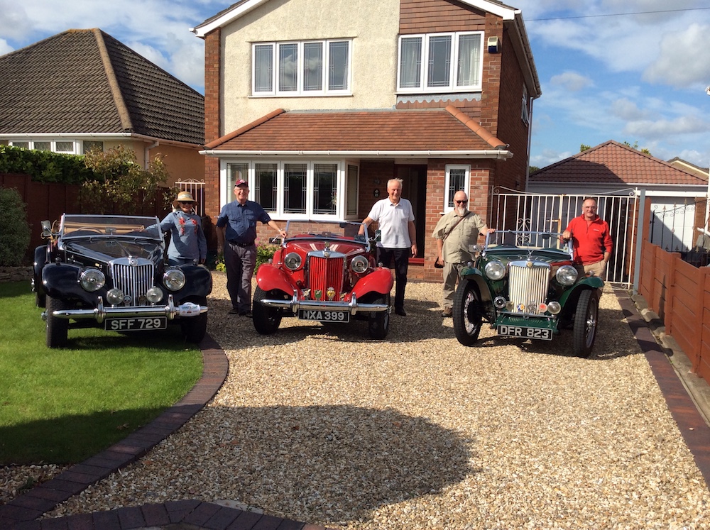
Who says a ‘love triangle’ will not stand the test of time?
Above: The way we were – the 3 newly weds 1971. Below: The way we are now – still the 3 newly weds 2019.
Having
grown tired of attempts to get his SU petrol pump working reliably,
Steve Priston decided to fit a Facet pump. Here’s what was
involved….
Having
had the standard AUA 25, SU fuel pump fail on my TC, I tried to cure
its reluctance to keep going by fitting some new contacts; but the
best that I could get from it was something that must have sounded
like a WW2 airborne dog fight, in the distance. Unfortunately for me,
despite hours of persevering with the diaphragm positions, the guns
kept stopping briefly, as the SU tried to save its ammo!
The
pump had caused problems before, by the tell-tale chewed-up screw
heads, so it was time for a replacement; but rather than blindly
fitting the same thing, it was time for some research to see what
other people had been doing to their cars.
A
Riley man, a friend of a friend, had fitted a modern, American made
Facet fuel pump, by his tank, with a return fuel line, back from the
engine bay, connected to the tank’s filler neck. This worked for him,
despite not having a regulator or even a flow restrictor on its
return line.
A
very good friend, a V8 Morgan owner, had fitted his Facet pump, also
close to the fuel tank, but this time a pressure regulator, made by
Malpassi was used. This was able to regulate the supply pressure,
having a range of between 1.5 & 5 psi, easily adjusted, via a top
mounted screw, with a lock nut. He had seen the fuel boiling, in the
glass filter bowl on his regulator, whilst positioned under the
bonnet, so had moved it to the rear of his car, near the pump!
This
second version seemed to be the way to go, not having to worry about
a return line to the tank, but just requiring a means of mounting the
two major components close to the TC’s tank; however not too close,
in the case of the regulator, which was not going to have a filter.
I don’t like drilling extra holes in anything, if it can be avoided, so after much head scratching, with the new pump being offered about, I decided that I would use the nearside rear axle bump stop fixing holes. I then cobbled-up an alloy bracket, from a piece of off cut angle, mounting it under the top of the chassis rail to be held in place by the nuts of the bump stop bracket.
In this picture you can see the alloy bracket (shown in the previous picture) secured in position by the nuts of the bump stop bracket. Once secured, it acts as the mounting bracket for the pump.
An
overhead view of the arrangement.
Apparently
there is a preferred way to mount this type of pump, to avoid any
issues with cavitation, which is for the flow to be upwards and for
the pump to be at a 45 degree angle. So that was my target, proving
to be ideal for connecting to the existing copper line, from the
tank, which travels along the outside of the nearside chassis rail.
The
pump in question is listed as negative earth, as I believe are all of
their pumps, but this could be overcome by using rubber mounting
blocks, along with plain, non-conductive rubber tubing. In fact, this
model has a plastic outer casing and when I put a meter across the
inlet filter/outlet hose tails, there was no continuity.
The regulator comes with its own bracket, which requires bending so that it remains horizontal when screwed to the plywood as shown; the use of a 90 degree hose tail, making for a good alignment, with the copper fuel line, which needs about 18 inches cutting out under the axle, with a little bending to suit.
The pressure regulator screwed to the ply behind the lower part of the seat back backrest.
Of
course, it will need wiring and a 5-amp fuse, which to me is not my
bag but had to be done whilst laying on my back, when an ice cream
would have struggled to melt quicker than I was!
Having
altered the float chamber tops some time earlier (see
later text),
it raised concerns over the possibility of rupturing part of the fuel
supply system after the pump, especially above that damned exhaust,
should the car be involved in a frontal impact, so I have fitted a
second-hand inertia switch, from a Rover. I think that the same model
is used on many cars but I doubt they are fitted just up the back of
the dash, on the passenger’s side.
I
remember hearing about the position used by Ford, in their early
Mondeo estate cars, not enjoyed by a friend, with a fully loaded
boot, when he stalled it so violently, that the switch was activated,
in heavy traffic, on a motorway!
I
would say that this is all straight forward work, best undertaken
when the weather is a little cooler so the sweat doesn’t fill the
lenses of your glasses!
Sourcing
the parts
Once
again ‘good old’ eBay again came into its own to find what I
needed cheaply and to get it quickly. Surprisingly, the cost of all
this lot is similar to or cheaper than, that of an original type SU
pump but the Facet was only £32 including postage, rated at 6,000
hours.
A
Facet PRO243-K pump.
A
Malpassi FSEFPR008B regulator, with 8mm hose tails.
A
pair of Syntec FPA rubber mounts, although longer ones would be an
advantage.
A
pair of Syntec NPT Fine, 90 degree, 8mm hose tails.
Some
8mm / 5/16″ bore non-overbraided fuel hose and clips.
Prior to this pump replacement, I had already decided to see what I could do to improve matters with hot fuel under the bonnet. The fuel hoses to the twin carburettors were re-routed by swapping the float chamber tops over. This enabled me to run the feed to the front float chamber around the back of the air cleaner, so that being nearer the bonnet louvres, it was away from being directly above the exhaust manifold.
Re-routing
of the fuel hoses to keep the carb to carb hose as far away as
possible from the exhaust manifold.
I
also wondered why the hoses from the SU pump and between the float
chambers, were such a large bore size, when later cars employing a
similar SU set-up, had either 1/4″ or 3/16″ bore tubing.
So, I made some new hoses in 6mm bore, reducing the hose stored fuel
volume, by around 40% per inch, but now with a further reduction as a
result of removing the contents inside the SU pump as well.
Ed’s
note: The old fuel hoses which
were replaced using new hoses of a 6mm bore had a bore size of 8mm.
Steve now has a 35 inch length of fuel hose under the bonnet, instead
of a 29 inch length.
The
above, to my mind could only but help with the problem of vapour
lock, caused by so much fuel being heated under the bonnet, as its
volume has been reduced. The smaller bore hoses also increase the
fuel velocity from the pump so it is not exposed to the heat for so
long either; at least that is my view!
To finish off, I saw the original mounting position for the SU pump, to be where logically, the coil should now be mounted, no longer tucked partially behind the rocker cover and in a position that nicely disguises the missing pump from the bulk head, and also nearer to the louvres.
The
coil now re-positioned to where the SU pump was originally located.
Since
this work, I have adjusted the fuel regulator a couple of times, now
being just two turns up, from being fully home, having only five
turns of adjustment.
The
engine idles beautifully, especially when hot and I have now adopted
a way of starting the car, after it has been parked for as long as it
takes to eat a nice cake and ‘down’ a decent coffee. This is to
simply to pull the starter, then let it idle for a few moments,
whilst the oil pressure goes up, before driving away, hopefully now
without any drama or embarrassment.
Steve Priston alerted me to the following details about connections to the coil.
Firstly, his experience of the running of his TC before and after the coil connections were swapped and secondly, John Saunders’ technical explanation.
Over to Steve………
“My
1948 TC did not like climbing the last part of a local, long but
gradual incline, something that I had attributed to the much talked
about modern fuel related problems.
It
would easily maintain just over 3000 rpm, for two thirds, to three
quarters of the climb, then really protest, causing me to rapidly
lift off the accelerator, then after a short pause, gradually
re-apply it, in doing so, losing a lot of momentum but all seemed
well again.
I
experienced this in a more dramatic way, when climbing another long
hill but this time, requiring the use of third gear, holding 3500rpm,
for the duration of the climb, knowing that the under-bonnet
temperature would be high, again thinking fuel was the cause.
Then,
as we have been experiencing higher ambient temperatures, my
previously smooth engine, had developed a noticeable but slight
harshness, felt through the accelerator pedal, when cruising on the
flat, at 50mph, which earlier in the year, had certainly not been the
case.
Having
previously been assisted by John Saunders, drawing on his experience
gained from living with a TC, I contacted him for his thoughts on my
problems. I was quite taken aback by his response and the speed with
which it was given and I immediately went to the car, still with him
on the phone, with a torch and mirror in the other hand, to see how
my coil was wired.
The
phone was left on the battery box lid, for a moment, whilst I checked
and sure enough, based on John’s own findings, my coil was wired
incorrectly!
A
couple of days later, having come off shift, I swapped the wires to
the coil and out I went, heading for that damn hill again. No
problems this time or traces of harshness from the engine – what a
relief and thanks to John Saunders for the correct diagnosis.
I
then delved through the paperwork, that had come with the car, to see
when the coil was last replaced and who was responsible. It turned
out to be the same company, that I discovered had claimed to have
also replaced the condenser, which was definitely still the one
fitted at the factory or by Lucas, by the superb standard of
soldering!
The
receipt was from 14 years ago, the car having covered 4000 miles like
it, so I decided to treat it to a new Bosch coil, from Euro Car
Parts, costing £20, just for peace of mind.”
Ed’s
note: John
Saunders‘ technical explanation and a diagram follows:
When
the MG TC was new, if an ignition coil was to be retired for any
reason, the replacement coil would be marked SW (for switch) on the
low tension terminal receiving current, at 12 volts, from the battery
negative terminal, through the ignition switch.
The other low tension terminal would be marked CB (contact breaker) and would be connected to the distributor low tension terminal, and thus grounded intermittently through the CB to the positive vehicle earth (see the diagram which follows).All this is well known and is not disputed or controversial.
Now step forward to modern times when all new vehicles are negative earth, and you will find, unless you buy a special coil marked SW and CB, that the coil low tension terminals are marked + and -. You will normally not receive with your purchase an illustration showing the coil internal electrical circuit arrangement as in the diagram which follows.
You will probably and understandingly connect the negative low tension coil terminal to the 12 volt negative supply terminal and the positive coil terminal to the positive distributor terminal. This is perfectly logical, but for any positive earth vehicle (e.g. MG TA, TB and TC) is exactly WRONG!
The reason is that when
the coil terminal marked
“–“
is fed directly from the
battery, via the ignition switch, the coil primary winding carries
the full battery output to earth, through the contact breaker, with a
higher current load the faster the car is run. This quickly leads to
significant overheating of the coil and missing ignition pulses, and
ultimately to an internal short circuit in the high tension coil and
complete coil failure. This has happened to me twice, necessitating a
tow home by a friendly neighbor each time.
So,
what’s to do? Very simple; ignore the polarity markings on the new
coil and install it with its “+” side toward the battery/ignition
switch supply side and the “–“ terminal connecting with the
distributor (CB). When the LT terminals are connected in this
fashion, the current is fed to both the low tension LT coil and to
the high tension HT coil, by the internal design in approximately
equal proportions, thus halving the LT heating effect.
It
will pay to check the resistance between the low tension terminals.
For a TC in normal use, i.e. no competition, using about 5,200 RPM as
a maximum, the resistance should be around 3.3 to 3.6 ohm. If it is
about 2.6 ohm, as my new coil, use a ballast resistor; I have 0.8 ohm
ballast fitted. An LT resistance of about 3.6 ohm should be fine for
a normally used TC.
You can check coil temperature with your hand; warm to very warm is fine, too hot to touch is trouble.
It is about 9 years since I installed a supercharger on my 1953 TD and once fitted I wrote an article for TT Type 2 (August 2011} and the Octagon Bulletin (October and November 2011}. Nothing technical but just a record of my experiences and thoughts.
The supercharger and fittings were supplied by Steve Baker and we fitted it together. I say “we” but in reality, he did 80% of the work and I acted as apprentice mechanic and second pair of hands.
Subsequently I met Steve and his son Luke at the Stoneleigh MG event about 4 years ago when my car was on the MG Octagon Car Club stand. We had a good chat, during which time I promised to write a follow up article. This is it, albeit a bit later than intended! Rather than repeat what was written previously I thought that answers to the questions I get asked most frequently might be of more interest.
Why did you fit one?
As a kid I read all of Ian Flemings’ James Bond novels and the books mentioned the whine of the supercharger on Bond’s old Bentley. It sounded very exotic to me and that sparked the wish to one day own a car with one fitted.
What preparation was necessary?
The engine had not done too many miles since a rebuild so the compression was checked. As all cylinders were pretty much the same the only additional work was to replace the core plugs after thoroughly flushing the engine and radiator. I added a second fuel pump to mirror the TD MarkII layout, but in hindsight this was not necessary as a single pump would have coped. The gear box was rebuilt at the same time as this had been playing up.
Did you upgrade the brakes?
No, the twin leading shoe system on the car has been quite adequate for road use.
What maintenance does it require?
The unit fitted is an Eaton 45 and does not require any particular maintenance. As a precaution I do check the drive belt and all the pulleys and fittings regularly.
Why
did you choose this supercharger?
I set out to get a period Shorrocks but couldn’t find one. This was available and as a complete kit, which is well engineered. Also, it looks very similar to a Shorrocks and coupled with the fact the maintenance regime is negligible, made the choice a simple one.
Has
it impacted fuel consumption?
The simple answer is yes. Driving sensibly the car will return a little over 30 mpg. However, that doesn’t happen very often as it is far too much fun not to drive enthusiastically.
What is it like driving the car with a supercharger?
Not surprisingly, the acceleration is much improved and so is the torque, making the driving easier, perhaps requiring fewer gear changes. The normal engine running temperature has dropped from around 85 degrees to 78-80. It rarely gets above 85 even on a hot day or after a fast run. Starting in winter requires full choke but only for a very short while and in the summer very little, if any. Otherwise the TD gives the same pleasurable drive as always. The supercharger does whine, but quietly and only at higher revs.
Have you fitted a 5-speed gearbox or altered the differential to reduce the rev’s at higher speeds?
Not yet. I have been contemplating fitting a 5-speed gearbox for a while but haven’t found the time (nor the cash) to carry out the work. That job may have to wait until retirement.
Would you ever revert to the standard carburettor set up?
Not if can help it!
Colin Hooper August 2019
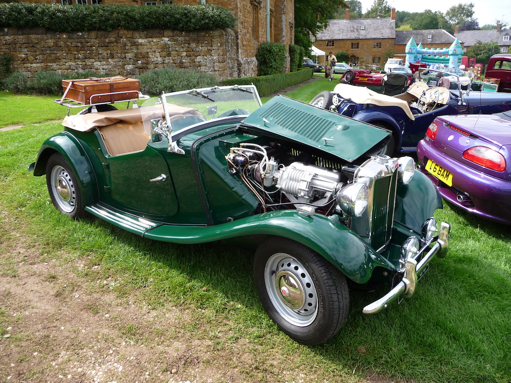
Colin’s TD pictured at a show soon after the supercharger was fitted.
Eaton M45 XPAG Supercharger Kit. £3,650.00 inclusive of VAT. The kit is supplied with fitting instructions and includes all necessary parts for installation, including a 1.5 rebuilt SU carburetor. The kit is set up for 6lbs boost suitable for fast road use.
Steve asks that you contact him in the first instance before ordering online.
This website uses cookies to improve your experience. We'll assume you're ok with this, but you can opt-out if you wish. Cookie settingsACCEPT
Privacy & Cookies Policy
Privacy Overview
This website uses cookies to improve your experience while you navigate through the website. Out of these cookies, the cookies that are categorized as necessary are stored on your browser as they are essential for the working of basic functionalities of the website. We also use third-party cookies that help us analyze and understand how you use this website. These cookies will be stored in your browser only with your consent. You also have the option to opt-out of these cookies. But opting out of some of these cookies may have an effect on your browsing experience.
Necessary cookies are absolutely essential for the website to function properly. This category only includes cookies that ensures basic functionalities and security features of the website. These cookies do not store any personal information.
Any cookies that may not be particularly necessary for the website to function and is used specifically to collect user personal data via analytics, ads, other embedded contents are termed as non-necessary cookies. It is mandatory to procure user consent prior to running these cookies on your website.