
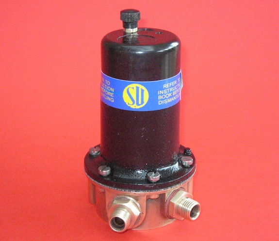
Part 1 of this article published in the June 2011 edition of TTT 2 will have helped you to identify the various versions of SU’s ubiquitous Type L pump. Part 2 will take you through the steps to refurbish your pump.
1. Dismantling
When dismantling the pump take care not to damage the coil connections that emerge from the coil housing. These are fragile, especially if the pump is an older brass-based version. The method described below should cause the minimum disturbance of these leads. If the leads are broken it may necessitate removing the coil from the housing which complicates the refurbishment significantly.
Any screws that are seized should be loosened with the use of a release fluid rather than risk snapping off a head leaving the screw seized in situ. The most effective release fluid is a 50-50 mix of automatic transmission fluid and acetone. I always use new 2BA screws to rebuild a pump, which are readily available from Namrick.
contact blade.”
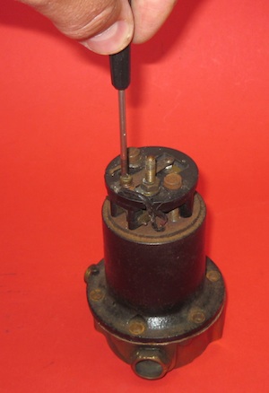
1.1 Remove the terminal knob, the 2BA nut that retains the cap and any tape sealing the cap to the body. Retain the knob and the 2BA nut for re-use. Loosen the 5BA screw holding the contact blade. Remove and discard the old contact blade. Loosen and pull out the rocker hinge pin that fixes the rocker mechanism onto the pedestal. Use release fluid if the pin is seized.
1.2 Remove the five 2BA screws and the earth terminal post (or six screws on later pumps) that hold the coil housing onto the pump body. Separate the pump body from the coil housing. Separate the diaphragm from the coil housing using a knife blade if necessary. On later alloy based pumps separate the two halves of the pump body. Collect the eleven brass rollers that centralise the diaphragm in the coil housing and retain for re-use. Unscrew the diaphragm from the rocker mechanism and discard the old diaphragm and the volute spring. Take care handling and disposing of old gaskets, which may contain asbestos.

out old rocker mechanism”.
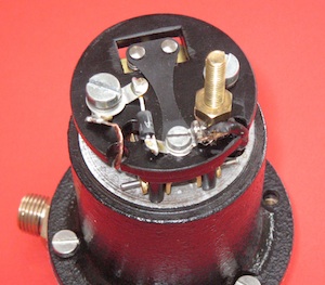
1.3 Loosen the two 2BA screws that fix the pedestal to the coil housing. Remove the screw connected by a braided wire to the rocker. Raise the pedestal carefully and slide out old rocker mechanism. Replace and tighten the two 2BA screws temporarily to protect the pedestal and the coil connections whilst cleaning the coil housing.
1.4 Remove the inlet and outlet connectors from the pump base together with the filter retainer. Use the correct spanner to avoid damaging the soft brass parts. A 3/8 BSW ring spanner is a perfect fit. If the filter is a wire mesh type and is undamaged retain it for re-use as the replacement plastic filter supplied by Burlen is slightly larger and a difficult fit. Pull out the outlet valve cage from beneath the outlet connector and discard it all, except the spring clip that retains the top valve plate. Finally, remove the valve disc and the washer from beneath the valve cage.
2. Cleaning
2.1 The next step is to clean the retained parts for reuse. The base and brass connectors parts can be cleaned either by bead blasting or by scrubbing in diluted hydrochloric acid which is sold in DIY stores as ‘brick cleaner’ for removing cement stains from brickwork. I prefer the latter method as bead blasting alters the appearance of the soft metal parts, leaving them pitted. The object is to remove the dirt, not the surface layer of metal. Take all sensible precautions when using any aggressive chemicals. As a minimum wear disposable plastic gloves and eye protection. Avoid breathing any fumes. Don’t be tempted to polish brass parts on a buffing wheel if you have one. They never shone like the buttons on a guardsman’s tunic. If you have the later steel connectors they can be cleaned with a wire brush but they will rust if the plating is removed.
2.2 The plastic cap, the pedestal and the terminal nut can all be cleaned with mildly abrasive car polish such as ‘T Cut’.
3. Painting
3.1 The only part to be painted is the coil housing. Remove any rust and dirt with a stiff wire brush and then apply a coat of black paint. I use a coat of mild etch primer. Take care not to let paint block the vent hole positioned between two of the 2BA fixing screw holes. After the paint has dried remove any paint from the bottom face of the coil housing by rubbing on a sheet of abrasive paper.
4. Rebuilding the Pump
4.1 The first step in rebuilding the pump is to obtain the correct repair kit from Burlen Fuel Systems. For pre-1985 Low Pressure pumps you need EPK 700. For later pumps you need EPK 705. For the long bodied High Pressure AUA54 pump fitted to most TFs you need EPK 601, which has an extended diaphragm spindle. For all other high pressure pumps Burlen specify EPK 600 for negative earth cars and EPK 605 for positive earth cars but either will suit if you plan to fit a Transil (see para 4.12). The contents of an EPK 700 kit are shown below. The group of parts on the right is not required.

4.2 First, fit the recovered and cleaned filter to the filter retainer. Fit the retainer and filter to the pump body using one of the buff coloured washers provided in the kit to seal it in place. If you are using the plastic filter provided in the Burlen kit you will find it is too big to fit easily into the retainer. If you manage to fit it to the retainer drive it fully home by tapping it smartly on the work surface. To assist fitting the plastic filter into the pump body remove any moulding marks from the top edge and lubricate it with grease. If the top of the filter is unable to rotate in the pump body as the retainer is tightened it will twist and be destroyed.

making sure its two spring ‘ears’ are
uppermost, away from the disc.”
4.3 Insert one of the new valve discs into the outlet valve cage. Fit the recovered retainer spring clip, making sure its two spring ‘ears’ are uppermost, away from the disc. N.B. some valve discs have a plain surface on one side and a patterned surface on the other. Always fit the discs with the plain surface to the valve seat.
4.4 Inspect the inlet valve seat inside the pump body. Make sure it is free from scores and corrosion that will prevent the valve sealing correctly. If necessary polish the seat with a small piece of fine wet and dry paper stuck onto the end of a pencil or wooden dowel.
4.5 Drop the second valve disc onto the polished inlet valve seat. Fit the ‘thin’ fibre washer into the valve chamber and then drop in the outlet valve cage assembly. Insert a buff washer on top of the cage and finally fit the outlet connector. Fit the inlet connector to the pump body using the red fibre washer. Tighten the connectors and the filter retainer using the correct spanner.
4.6 Fit the new rocker mechanism to the pedestal and fix it in position with the hinge pin provided. Before fitting the mechanism it may be necessary to ‘square up’ the parts so that it is a good fit around the legs of the pedestal. Fit the contact blade to enable the rocker clearances to be set. Carefully tighten the 2BA pedestal fixing screws. Don’t over tighten them or the pedestal will crack. They should be sufficiently tight to fully compress the spring coil washer but no tighter.
4.7 Using a set of feeler gauges first set the height by which the rocker lifts the contact blade off the pedestal. This should be set to 0.9mm (0.035 inches) by bending the top stop tab on the rocker as it is pushed upwards. Then set the gap between the bottom foot of the rocker and the coil housing, again with the rocker pushed upwards. This should be 2.3mm (0.09 inches) and is adjusted by bending the foot to suit. After making these adjustments remove the contact blade again to enable the diaphragm to be set correctly.
4.8 Fit the volute spring to the diaphragm and fit them to the coil housing with the narrow end of the spring to the diaphragm. As the diaphragm spindle is inserted into the coil housing the threaded top must be engaged with the threaded crossbar of the rocker. This is a tricky operation only because it is difficult to see what is going on but becomes easier with practise!
4.9 To adjust the diaphragm continue to screw the spindle into the rocker cross bar whilst pressing and releasing the diaphragm to ‘throw over’ the rocker. Eventually as the diaphragm is screwed home the diaphragm will stop throwing over. In reaching this point make sure the diaphragm is centralised in the coil housing and not jammed off centre. When the diaphragm no longer throws over unscrew it until it just throws over as the diaphragm is pushed and released, then a little further, if necessary, until the holes in the coil housing and the holes in the diaphragm align. Note this position and unscrew the diaphragm a further two-thirds of a turn, or 4 screw holes. Don’t let the diaphragm rotate again from this final position.
4.10 Fit the rollers recovered from your old pump to centralise the diaphragm in the coil housing. You will find that the replacement ‘figure of eight’ spacers supplied by Burlen are too large to fit. They lock the diaphragm solid. I’ve told Burlen, but they aren’t at all receptive.
4.11 Now screw the coil housing and diaphragm onto the refurbished base. Note the correct rotational relationship. The drain hole in the coil housing should be adjacent to the filter retainer. If you have a brass based pump there is no need to use a gasket. If you have a two-piece alloy base just use the gasket between the two halves of the base. Leave the screws loose, as the diaphragm must be stretched before the screws are tightened. Do this either by lifting the inner part of the rocker with a screwdriver or by applying 12 volts to the coil leads. Screw up the six 2BA screws whilst the diaphragm is under tension.
4.12 Finally refit the contact blade and a Transil* to protect the points. Ensure the blade contacts align with those on the rocker. Tighten the 5BA screw holding the blade in place. Fit the cap. Check all the connectors for tightness. Fit tape or a label to seal the cap to the body to exclude dust and moisture.
5. Testing
The best way of testing the refurbished pump is described in the TD/TF workshop manual. Without the test equipment described therein the application of 12V between the top terminal and the body will confirm that all is well. Check for leaks when first using the refurbished pump and retighten the 2BA screws or connectors if necessary.
Eric Lembrick
* Transil kits are available from Peter Cole pcoleuk ‘at’ gmail.com whose assistance with this article is acknowledged.
EPK 700 kit.how much,this pocet cost.
and can yu send this pocet to Finland.
hello tipi
One confusing point. Mentioned are Burlen kits for TC/TD, EPK 700 for pre 1985 pumps, EPK 705 for post 1985 pumps, and EPK 601 for the long body TF pump. I noticed in the U.S. Moss catalog that four different diaphragms are listed for TC-TF. One listing for the 2 3/8″ stem TF pump…confusion begins…three other listings TC/TD; described as 1. for pre-1985 replacement pump with 2 3/8″ stem., 2. for post 1985 replacement pumps 2 3/8″ stem., and 3. for original pumps 2 15/16″ stem. Does one tell if one has an “original” TC/TD pump by having a 2 15/16″ stem diaphragm? Do the brass bottom pumps use longer stem? Does this article imply most all pumps are pre or post 1985 replacement pumps, or is Moss catalog confused? Also, I thought I have an original (late) TC pump, but it seems to have a 2 3/8″ stem diaphragm…unless you measure the entire diaphragm sitting on a table– to tip of stem at right around 2 15/16 inch. Confusing? The old diaphragm is a reddish color and has a metal step, between which go the 11 brass fitment washers. Can anyone straighten this out for me, please?
I am not familiar with the diaphragms mentioned by Moss US but the reference point for all SU parts should be Burlen Fuels Systems. Burlen owns the SU brand and produce the only genuine SU spares.
They list the EPK 600 pump repair kit for high pressure pumps used in negative earth (ground) cars, EPK 605 kit for high pressure pumps used in positive earth cars and the EPK 601 kit for long bodied pumps (as fitted to late TFs) of either battery polarity. They list the EKP 700 kit for pre-1985 low pressure pumps and the EPK 705 for post-1985 pumps.
As far as diaphragms are concerned the long bodied HP pump as fitted to the rear of the chassis of most TFs uses a unique diaphragm with a longer spindle which is approximately 3 inch long, as measured from the spindle side of the diaphragm. This is part number AUB 6099.
Very early TFs and all other T Types used a shorter bodied low pressure pump mounted on the bulkhead. These all had a diaphragm with a shorter spindle which is approximately 2 3/8 inches long. At the time these pumps all used an AUB 6098 diaphragm. Brass base pumps (fitted up until 1948) and post-1948 alloy base pumps both used this diaphragm.
From 1985 the lines between the low pressure pump and the high pressure pump blurred somewhat. In September 1985 SU started to produced a new coil housing which was common to both pump types. This coil body had a 4BA earth screw and minor casting differences. It is not correct for T Types which of course were all made long before 1985. The low pressure version of the post-1985 pump uses an AUB 6082 diaphragm and the high pressure version an AUB 6097 diaphragm with a different spring. Both these diaphragms have a shorter 2 3/8 spindle. Whilst not correct for the purist the appropriate post-1985 pump will operate perfectly well in a T Type, and most people wouldn’t be able to spot the difference.